
Summary of Version 2.0 Arduino Controlled Car Tracking System based on SMS
This article details the construction of a GSM-based car tracking system using an Arduino Pro and Wavecom modem. The device sends SMS messages containing GPS coordinates and a Google Maps link upon receiving a call. Key steps include configuring the Wavecom module's baud rate, assembling a custom data cable, connecting the GPS and RS232 modules to the Arduino, and securing components with silicone. A buzzer is added for status confirmation, and the system is powered via a wireless RF switch.
Parts used in the Version 2.0 Arduino Controlled Car Tracking System:
- TTL to RS232 Module
- VGA socket
- SkyLab SKM53 GPS Module
- Arduino Pro
- Wavecom GSM modem
- Buzzer
- Wireless RF switch
This system is upgraded version of previous project…
You will be able to track your car after you build this system,
you will call the device then it will send you an sms which includes LAT, LON and Google Map link for just one touch to see where it is.
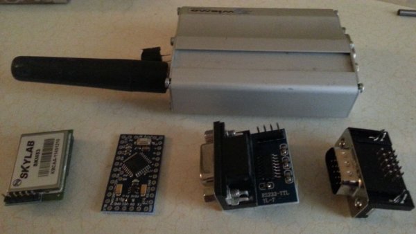
Before you start to build them, you should connect the Wavecom to PC to adjust Serial Com. Baud Rate to 9600
then make it save this configuration via AT commands. (It is written in Wavecom AT command datasheet).
Step 1: Preparing the Wavecom For fastening the modules
Secondly, disassemble the wavecom GSM module and drill many holes for screws, our modules hold on these screws..
Step 2: Preparing the Datacable
Let’s make a datacable between Wavecom and RS232 module,
you use just 3 pinouts, it’s enough for communication..
Step 3: Connecting the other parts
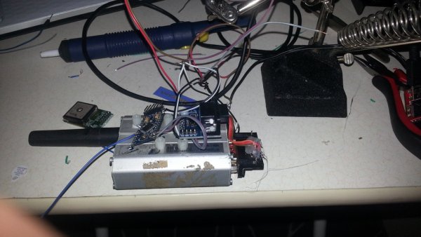
Now let’s connect the RS232 and GPS module to our Arduino,
We use 3 pinouts of GPS module ,
These are TX, VCC , Ground (on Skylab SKM53).
connect
GPS TX pinout —-> Arduino PIN 5
RS232 Module RX—> Arduino PIN 10
RS232 Module TX—> Arduino PIN 11
also do not forget to connect Vcc and GND pinouts of RS232 module, GPS module and Arduino
Step 4: Finishing the Tracker Device
Not fix these modules on Wavecom with silicon…
You also can connect a buzzer to PIN7 , I do it because I’ll put this device in a hidden place then power it on/off with wireless RF switch. So, I can hear the buzzer when I power it on..
Now .. upload program on arduino.. (next step)
TTL to RS232 Module
VGA socket
SkyLab SKM53 GPS Module
Arduino Pro
Wavecom GSM modem
For more detail: Version 2.0 Arduino Controlled Car Tracking System based on SMS
- How do I configure the Wavecom module before starting?
You must connect the Wavecom to a PC and adjust the Serial Com Baud Rate to 9600 using AT commands. - What pins are required for communication between the Wavecom and RS232 module?
Only three pinouts are needed to establish communication between the Wavecom and the RS232 module. - Which Arduino pins should be used for the GPS and RS232 connections?
Connect GPS TX to Arduino PIN 5, RS232 RX to Arduino PIN 10, and RS232 TX to Arduino PIN 11. - How can I verify the device is powered on if it is hidden?
You can connect a buzzer to PIN 7 to hear a sound when the device powers on via a wireless RF switch. - What information does the system send via SMS?
The system sends an SMS containing LAT, LON, and a one-touch Google Map link. - How are the modules secured inside the tracker device?
Modules are fastened using screws drilled into the disassembled Wavecom casing and held with silicone. - What is the purpose of the VGA socket in this project?
The VGA socket is listed as a required material component for the major parts list.
