Summary of Using NXT Components With a Micro Controller
This article provides a comprehensive guide on interfacing LEGO NXT motors and sensors with the Parallax Basic Stamp II (BS2) microcontroller, offering theoretical insights beneficial for other platforms like Arduino. It details cable preparation, pinout configurations, and coding strategies for touch sensors and motor encoders to control speed and direction.
Parts used in the LEGO NXT Microcontroller Project:
- LEGO NXT set motors
- LEGO NXT sensors
- Parallax Basic Stamp II (BS2)
- NXT cables (stripped or modified RJ-12)
- Solid-core wiring
- Soldering iron and heatshrink tubing
- H Bridge
- Female jack from Mindsensors
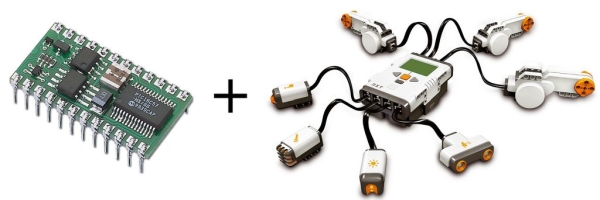
This is a guide to using the motors and sensors from the LEGO NXT set with a Parallax Basic Stamp II or BS2. However, rather than just providing schematics and sample code for the BS2, I’ll be providing some theory on how the sensors work as well. This way, someone using an arduino or other microcontroller should find this guide at least somewhat helpful.
My two main sources of information are
The LEGO Hardware Developer Kit http://mindstorms.lego.com/en-us/support/files/default.aspx
TheCompBlog: Hacking the NXT http://www.thecompblog.com/2012/07/hacking-lego-nxt-part-1.html
-The latter is a decent guide if you’re using an arduino. But take note that his schematics often show pins 2 and 3 connected to +5V instead of ground. Pins 2 and 3 are ground for all of the sensors except the button which is just a switch.
Have any suggestions? Is something difficult to understand, incorrect, or missing? Leave a comment and I’ll see what I can do. I would like this instructables to be a comprehensive guide on using the BS2 with the NXT set. If you’re using a different microcontroller and you’re stuck, I may or may not be able to help but it doesn’t hurt to ask.
I hope to get an arduino soon, and if this guide does well I will post a complimentary guide for using the arduino with sample codes for that. Let me know if you’d like that.
Step 1: NXT Cables
First and foremost, we need to connect our NXT hardware to our microcontroller. There are a few ways of going about this.
I opted for stripping a set of NXT cables I ordered from http://mindsensors.com. I split up the wires, stripped them, soldered short lengths of solid-core wiring onto each, heatshrunk each solder joint, and heatshrunk the whole bundle of wires, creating a connector.
-In hindsight, you can buy one long wire and make two spliced wires out of it by cutting it in the middle.
-Also, make sure you keep your wires in order. The NXT wires are color-coded but the mindsensors wires are not.
-Some people have made modified RJ-12 cables and others have just worked with the originals.
Another option is to buy a female jack from mindsensors which requires little to no messing around with a soldering iron and looks a lot cleaner.
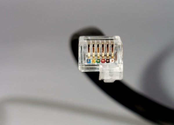
Wires are numbered from the latch side right-to-left, so the wire nearest the latch is 1 and the wire farthest from the latch is 6.
LEGO color codes them as follows:
1-White
2-Black
3-Red
4-Green
5-Yellow
6-Blue
(See image for reference)
Step 2: The Touch Sensor
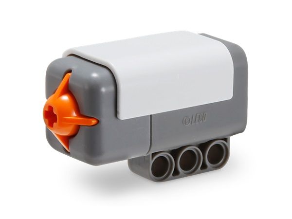
Let’s start with the touch sensor since it’s the simplest part. You can also use this to ensure you’ve got your wires in the right order. Using the touch sensor is very simple: it’s a normally open SPST switch, which basically means that it’s “on” when you push the button and “off” when you release it. Pin 1 is one terminal and Pins 2 and 3 are the other (use either or both). If it’s not working, you may have your wires backwards. Try using Pin 6 for one terminal and Pins 4 and 5 for the other.
Step 3: The Motor
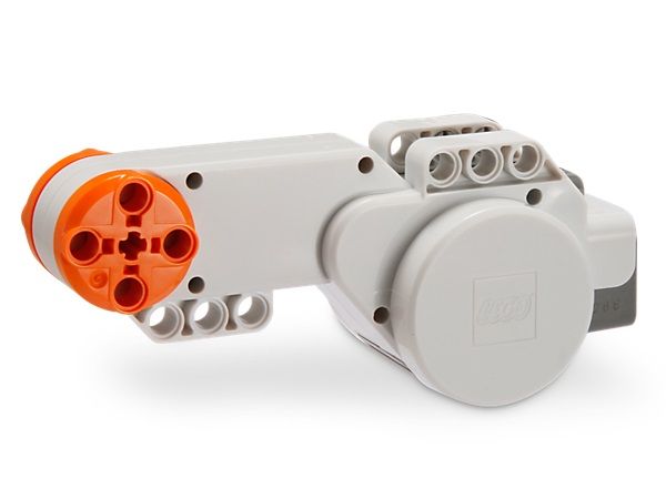
The NXT motor is a very nice piece of hardware and is also fairly easy to use. It features a 9V DC motor with a gearbox and a double encoder with a resolution of approximately 1 degree.
Pins 1 and 2 are the leads for the DC motor. Apply a potential, and the motor turns. Switch pins and the motor turns the other way. It’s that simple. I use an H Bridge for this.
The encoder is almost as simple. Pin 3 is Ground and Pin 4 is Vcc (5V). These supply power to the encoder. Pin 5 and Pin 6 are the two encoder outputs. In case anyone is unfamiliar with double encoders, here’s how they work:
Attached to the motor gearbox somewhere is an encoder wheel which has a bunch of radial slots in it. It turns with the rest of the gearbox. Two infrared sensors are placed such that the radial slots and spokes alternatively break and restore the IR beam, causing alternating 1’s and 0’s. So, when the motor is turning, either line will read 101010101010 at a rate determined by the rate of the motor. This is useful for speed and translation control. The more 1’s and 0’s, the farther you’ve gone. The faster it alternates, the faster you’re going.
So why do we need two encoders? For determining direction. Because the two IR sensors are offset, they output a pattern that is specific to direction of rotation. If the motor turns one way, they will output (Pin 5 Pin 6) 11, 10, 00, 01, repeat. If the motor turns the other way, the pattern is reversed: 11, 01, 00, 10, repeat. By watching the pattern, you can determine direction of rotation. I’d get specific about clockwise and counterclockwise, but it depends on how you hold the motor and is really easy to figure out on your own through experimentation.
Coding the basic stamp to use the encoder:
To determine the speed of the motor, I use the count function. Simply count the number of impulses from either of the encoder pins for a set period of time and you will get a number proportional to the speed of the motor.
COUNT Pin5, 100, speed
To wait for a certain number of cycles, I use a PULSIN command inside a for loop. The PULSIN makes the BS2 wait for the next pulse from the encoder before proceeding to the next step of the loop. This code will wait for n pulses. The variable “variable” is not important, but could also be used to determine speed in theory.
FOR i = 1 to n
PULSIN Pin5, 1, variable
NEXT
Determining direction is a little trickier. I have the stamp wait until the encoder reaches a specific step in the cycle such as 11 by using an if statement in a loop. Once the step has been reached, I check to see which step comes next (in this case, either 10 or 01) using a pair of if statements in another loop. Depending on which step comes next, you can determine which way the motor is turning.
It is also possible to use this method to passively measure the absolute displacement of the motor. Turning one direction will add to the displacement, while turning the other direction will subtract. This way, if you start at 0, turn the motor a certain angle, and turn it back, you should go back to 0 rather than the distance covered. This code checks direction once per cycle and then adds or subtracts 1 from displacement accordingly. It works at moderate rotational speeds, but not at high speeds due to the stamp’s clock speed.
pin5 PIN 1
pin6 PIN 0
disp VAR Word
loop1:
IF pin5=1 AND pin6=1 THEN direction ‘wait for 11 encoder step
GOTO loop1
direction:
IF pin5=0 THEN cw ‘See which pin goes low first to determine direction
IF pin6=0 THEN ccw
GOTO direction
cw:
disp=disp+1 ‘In this example, I made clockwise positive and counter-clockwise negative.
DEBUG ?disp
GOTO loop1
ccw:
disp=disp-1
DEBUG ?disp
GOTO loop1
I tried writing code to do this on a step-by-step basis so that instead of waiting for 11 to come around, it would check direction at each step for 4 times the accuracy. Unfortunately, the stamp doesn’t run fast enough for that. A faster microcontroller might be able to handle it. Here’s the code, but again it only works at very low speeds.
First, the code establishes which step the encoder is starting on and directs to the subroutine corresponding to that step.
Displacement starts at 1 due to an inherent fencepost error.
Each subroutine looks at what the previous step was. If the previous step was CCW of this step then the motor turned CW and 1 is added. Otherwise, CCW is default and 1 is subtracted. (Fencepost error occurs here but isn’t too important)
Next, the subroutine waits for the next step and then goes to the subroutine corresponding to that step.
It works very nice in theory but there are too many commands for each step so the BS2 can’t handle it fast enough.
a PIN 0
b PIN 1
lasta VAR Bit
lastb VAR Bit
disp VAR Word
disp=1
INPUT a
INPUT b
lasta=a
lastb=b
IF a=1 THEN a1
IF b=1 THEN S01
GOTO S00
a1:
IF b=1 THEN S11
GOTO S10
S01:
disp=disp-1
IF lasta=1 AND lastb=1 THEN disp=disp+2
DEBUG ?disp
lasta=0
lastb=1
S01Loop:
IF a=1 AND b=1 THEN S11
IF a=0 AND b=0 THEN S00
GOTO S01Loop
S11:
disp=disp-1
IF lasta=1 AND lastb=0 THEN disp=disp+2
DEBUG ?disp
lasta=1
lastb=1
S11Loop:
IF a=1 AND b=0 THEN S10
IF a=0 AND b=1 THEN S01
GOTO S11Loop
S10:
disp=disp-1
IF lasta=0 AND lastb=0 THEN disp=disp+2
DEBUG ?disp
lasta=1
lastb=0
S10Loop:
IF a=1 AND b=1 THEN S11
IF a=0 AND b=0 THEN S00
GOTO S10Loop
S00:
disp=disp-1
IF lasta=0 AND lastb=1 THEN disp=disp+2
DEBUG ?disp
lasta=0
lastb=0
S00Loop:
IF a=1 AND b=0 THEN S10
IF a=0 AND b=1 THEN S01
GOTO S00Loop
Read more: Using NXT Components With a Micro Controller
- How do I connect the LEGO NXT hardware to my microcontroller?
You can strip a set of NXT cables, solder solid-core wires to them, and use heatshrink tubing, or purchase a female jack from Mindsensors for a cleaner connection. - What is the wire color code for the NXT connector pins?
Pins 1 through 6 are color-coded White, Black, Red, Green, Yellow, and Blue respectively, numbered from right to left starting at the latch side. - How does the NXT touch sensor function electrically?
It acts as a normally open SPST switch that is on when pushed and off when released, connecting Pin 1 to Pins 2 and 3. - Can I reverse the direction of the NXT motor using this setup?
Yes, you simply need to switch the connections on Pins 1 and 2 which are the leads for the DC motor. - How does the double encoder determine the direction of rotation?
The two IR sensors are offset so they output specific patterns; one sequence indicates clockwise rotation while the reversed sequence indicates counter-clockwise rotation. - What command should I use to measure motor speed on the BS2?
You can use the COUNT function to count impulses from an encoder pin over a set period of time to get a number proportional to speed. - Why might high-speed displacement measurement fail on the Basic Stamp II?
The stamp's clock speed is too slow to process the step-by-step direction checks required for accurate high-speed measurements. - Where can I find additional resources for hacking the NXT?
The article cites The LEGO Hardware Developer Kit and TheCompBlog as main sources of information.