
Summary of Using an Arduino to Control or Test an SPI electronic device
This article details how to build and program a circuit using an Arduino Uno to test or control 8-bit SPI devices, specifically demonstrated with an Analog Devices AD7376 digital potentiometer. The setup involves reading 8-bit data from DIP switches via the Arduino and transmitting it to the peripheral device using the SPI protocol, including specific pin configurations and code implementation for MSB-first transmission on a rising clock edge.
Parts used in the Arduino SPI Device Test Project:
- Arduino Uno board
- Proto board
- DIP switches (8-bit)
- Analog Devices AD7376 digital potentiometer
- Connecting wires
- Arduino IDE software
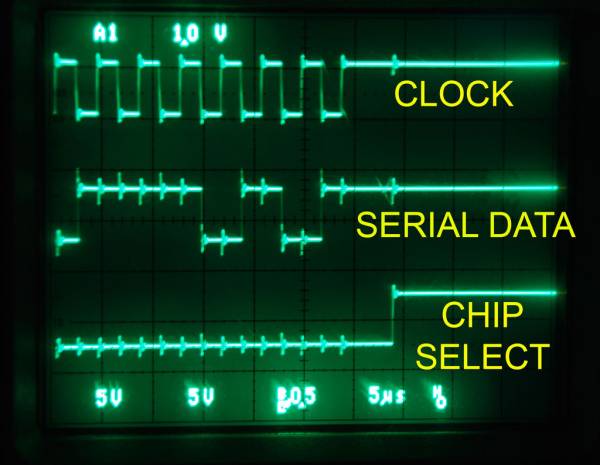
There are many electronic devices that use the SPI bus, or Serial Peripheral Interface bus, for communications (e.g. various sensors, LCD displays, digital potentiometers, D/A and A/D converters, wireless transmitters and receivers, audio volume controls). The devices receive data serially from a microcontroller using a 3-wire set-up that includes a chip select signal (usually titled CS – when this signal is at logic 0, a chip recognizes it will be receiving or sending data), a clock signal for clocking the serial data into the device, and the serial data stream itself.
Many hobbyists use microcontrollers such as the Arduino to control and use SPI devices. Oftentimes, you just want to test the electronic device to make sure it and its associated circuitry is working properly. This Instructables will show you how to set up and program a simple proto board circuit using the Arduino Uno to drive SPI data to a peripheral circuit which, in this case, is an Analog Devices AD7376 digital potentiometer. It could be any 8-bit SPI device using this circuit.
Step 1:
Assemble the Circuit: Place the Arduino board on the proto board in a convenient location. Next insert the DIP switches with all the pins on one side connected to ground (these DIP switches will provide the 8 bits of data that will be read by the Arduino and then sent serially to the AD7376). Wire digital pins 2 through 9 of the Arduino to the other side of the DIP switch, one wire per switch element
Step 2:
Next, look at the datasheet of the device you wish to drive to find its pin-outs. Then connect Arduino pin 13 to the SPI devices Clock pin, Arduino pin 11 to the SPI device’s SDI (Serial Data In) pin, and Arduino pin 10 to SPI device’s CS (Chip Select).
Step 3:
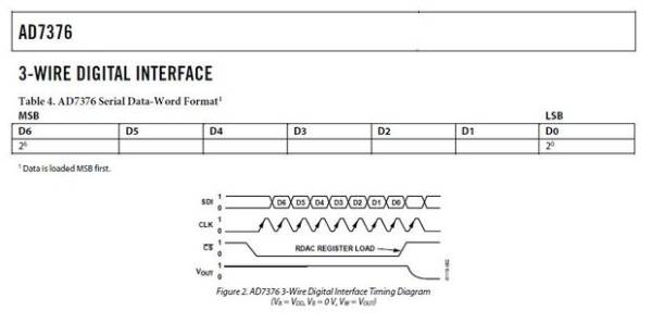
Next, you must set a few parameters on the SPI operation – whether the LSB (Least SIgnificant Bit) or MSB (Most Significant Bit) is sent first, if the data is clocked into the peripheral on a rising or falling edge of the clock, and if you want to slow the transmit speed of the data by reducing the frequency of the clock). This data is explained well on the Arduino site (www.arduino.cc) and in Wikipedia so will not be covered here. For this example, the MSB is sent first, it is clocked on a rising edge.
Step 4:
Now it is time for the software. You must download the Arduino IDE (Integrated Development Environment) from www.arduino.cc. This development tool allows you to write code that can be uploaded to the Arduino board and then executed.Insert the following code into the Arduino IDE. Note the comments in the code which tell you what each part of the code is doing.
/*
******************************************************
* SPI test (Driving a Digital Potentiometer in this case)
*
* This module uses the Arduino SPI library (comes bundled with
* the Arduino IDE) to enable communication between an
* Arduino program and an SPI enabled peripheral chip.
*
* The routine reads in 8 bit values, stores the value
* in variable “pot”, and then sends “pot” out via the SPI.
* *
* The SPI library uses pin 13 of the Arduino Uno for clock.
* Serial data is sent out on pin 11.
*
* This routine uses pin 10 as the chip select for the
* SPI device to be programmed.
*
* Pins 2-9 are used to read in values of the 8 bits for the byte
* to be sent via SPI
******************************************************
*/
#include <SPI.h> // Links prewritten SPI library into the code
void setup()
{
pinMode(2, INPUT); // Set pins 2-9 as inputs
pinMode(3, INPUT);
pinMode(4, INPUT);
pinMode(5, INPUT);
pinMode(6, INPUT);
pinMode(7, INPUT);
pinMode(8, INPUT);
pinMode(9, INPUT);
pinMode(10, OUTPUT); // Set SPI pins to be outputs
pinMode(11, OUTPUT);
pinMode(13, OUTPUT);
digitalWrite(2, HIGH); // Set Arduino pull-up resistors active
digitalWrite(3, HIGH); // This sets an internal to the chip
digitalWrite(4, HIGH); // pull-up resistor on so an unconnected pin
digitalWrite(5, HIGH); // is reliably at logic 1
digitalWrite(6, HIGH);
digitalWrite(7, HIGH);
digitalWrite(8, HIGH);
digitalWrite(9, HIGH);
digitalWrite(10, HIGH);
digitalWrite(11, HIGH);
digitalWrite(13, HIGH);
SPI.begin(); // Initialize SPI parameters
SPI.setBitOrder(MSBFIRST); // MSB to be sent first
SPI.setDataMode(SPI_MODE3); // Set for clock rising edge
SPI.setClockDivider(SPI_CLOCK_DIV64); // Set clock divider (optional)
// See Arduino site or Wikipedia for more info on these settings
}
void loop()
{
int val = 0; // “val” is a test variable used when reading pins
int j = 0; // “j” is a variable used in data read operation
byte pot = B00000000; // Zero all bits in byte “pot”
for (int i = 0; i < 8; i++) // Loop to read each of 8 input pins
{
j = i + 2; // Add 2 to loop count to match input pins
val = digitalRead(j); // Read appropriate pin
if(val == HIGH)
{
bitSet(pot, i); // Set appropriate bit to 1 based on loop count i
} // Otherwise leave it at 0
}
}
digitalWrite(10,LOW); // Drop SPI chip-select to 0 (Arduino pin 10)
SPI.transfer(pot); // Do SPI transfer of variable pot
digitalWrite(10,HIGH); // Raise chip-select to 1
delay(10000); // Delay loop 10 seconds (pick your time frame)
} // Data will be read and sent once every 10 seconds based on this
-
How do I connect the DIP switches to the Arduino?
Connect all pins of the DIP switches to ground on one side, and wire Arduino digital pins 2 through 9 to the other side of each switch element. -
Which Arduino pins are used for the SPI Clock and Data In signals?
Arduino pin 13 is connected to the SPI device's Clock pin, and pin 11 is connected to the SDI (Serial Data In) pin. -
What is the function of the Chip Select signal in this project?
The Chip Select signal, connected to Arduino pin 10, tells the peripheral device to recognize when it will be receiving or sending data when set to logic 0. -
How is the data bit order configured in the provided code?
The code sets the bit order to MSBFIRST so that the Most Significant Bit is sent first. -
On which edge of the clock signal is the data clocked into the peripheral?
The data is clocked into the peripheral on the rising edge of the clock signal. -
How often does the code transmit data to the SPI device?
The code transmits data once every 10 seconds due to the delay loop set to 10000 milliseconds. -
Can this circuit be used with devices other than the AD7376?
Yes, this circuit can be used with any 8-bit SPI device.
