Hi guys, welcome to today’s tutorial. Smart farms are becoming very popular as everyone is beginning to see the benefits in terms of crop health and yield and I know a lot of people that will be interested in smart farm automation. That’s why today, we will be looking at how to use a soil moisture sensor with an Arduino to determine the moisture content in the soil.
Soil moisture is generally the amount of water that is held in spaces between soil particles. It’s is a very important factor that determines the growth of crops and their health.
Instead of the old gravimetric method of measuring soil water content, the soil moisture sensor measures the volumetric water content indirectly by using other properties associated with the soil. The soil moisture sensor used for this tutorial uses electrical resistance of the soil to determine the soil humidity. The electrical resistance of the soil reduces with increase in the amount of water in the soil. The electrical resistance in the soil, however, increases with reduction in the amount of water in the soil. The sensor consists of a probe and a comparator with an adjustable potentiometer which can be used to set the sensitivity of the sensor.
Due to the desire and design techniques of different manufacturers, the sensor comes in different forms, cheap version of the sensor comes with a separate comparator board which is connected to the probe via jumper wires as shown in the image above, this version of the sensor always include an Analog to digital converter which allows the use of the sensor as a digital sensor. Other versions of the sensor from manufacturers like Sparkfun may have all the electronics attached to the probe. Irrespective of the sensor’s form factor, the connections, and use is the same.
Some of the features of this sensor include:
- Operating voltage: 3.3V~5V.
- Adjustable sensitivity (shown in blue digital potentiometer adjustment)
- Dual output mode, analog output more accurate.
- A fixed bolt hole for easy installation.
- With power indicator (red) and digital switching output indicator (green).
- Having LM393 comparator chip, stable.
- Panel PCB Dimension: 3cm x 1.5cm.
- Soil Probe Dimension: 6cm x 2cm.
- Cable Length: 21cm.
The probe of the sensor shown below consists of two large exposed pads that are used to test the electrical conductivity of the soil.
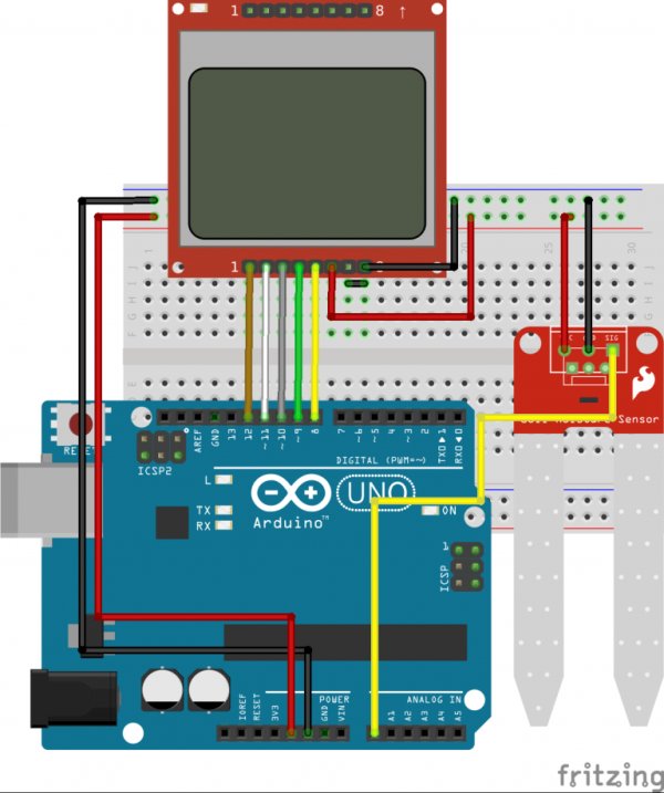
Our goal for this tutorial is to demonstrate how to use this interesting sensor by measuring the soil humidity and displaying the value either on the Arduino Serial monitor or on the Nokia 5110 LCD.
Read more: Using a Soil Moisture Sensor with Arduino