Summary of USING A 20×4 I2C CHARACTER LCD DISPLAY WITH ARDUINO UNO
This tutorial explains how to use a 20×4 I2C character LCD display with an Arduino Uno, highlighting its larger size and I2C communication that requires fewer wires. The project demonstrated is a real-time clock displaying date and time using the DS3231 RTC module. Both the LCD and RTC module communicate via I2C, connected through Arduino pins A4 (SDA) and A5 (SCL). The guide covers components, wiring, and usage, making it ideal for projects needing large text display and efficient wiring.
Parts used in the 20×4 I2C Character LCD Display with Arduino Project:
- Arduino Uno
- 20×4 I2C LCD Display
- DS3231 RTC Module
- Jumper Wires
- Breadboard
- Power Bank (or 9V battery with center-positive power jack)
On previous tutorials on our website, we have covered the use of several displays, LCDs, and TFTs, with diverse Arduino boards. From Nokia 5110 LCD display to different types of OLEDs, the reason for the tutorials has been to ensure that, as a reader, you know how to use many of the most popular displays so this help you make the best choice when trying to select the perfect display for your project. For today’s tutorial, we will continue in that line and examine how to use the 20×4 I2C Character LCD Display with Arduino.

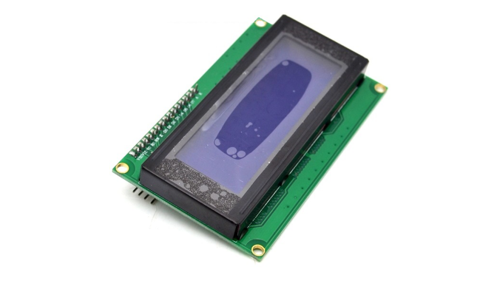
The 20×4 LCD display is essentially a bigger (increased number of rows and columns) version of the 16×2 LCD display with which we have built several projects. The display has room to display 20 columns of characters on 4 rows which makes it perfect for displaying a large amount of text without scrolling. Each of the columns has a resolution of 5×8 pixels which ensures its visibility from a substantial distance. Asides its size, the interesting thing about this version of the display being used for today’s tutorial is the fact that it communicates via I2C, which means we will only require 2 wires asides GND and VCC to connect the display to the Arduino. This is possible via the Parallel to I2C module coupled to the display as shown in picture below. The I2C module can also be bought individually, and coupled to the 16 pins version of the display.
A summary of some of the features of the LCD display is provided in the table below.
To demonstrate how to use this display, we will build a real-time clock which will display date and time on the LCD. To generate and keep track of date and time, we will use the DS3231 Real time clock. We covered the use of the DS3231 RTC module in the tutorial on DS3231 based Real-time Clock, you can check it out to learn more about its use with the Arduino.
REQUIRED COMPONENTS
The following components are required for this project.
The exact component used for this tutorial can be bought via the links attached and the power bank is only required to run the Arduino when not connected to the computer. You can replace this with a 9V battery and a center-positive power jack.
SCHEMATICS
Since the display and the real-time clock are both I2C devices, they will be connected to the same pins on the Arduino. For the Arduino Uno, the I2C pins are located on Pin A5 (SCL) and A4 (SDA). This may differ on any of the other Arduino boards. Connect the components as shown in the schematics below;
To make the connections, even more easier to follow, the pin connections of the components is described below.
Read more: USING A 20×4 I2C CHARACTER LCD DISPLAY WITH ARDUINO UNO
