Authors:
Bella Lax
Tianle Zhai
Alex Clark
With Help and Thanks To:
Professor Chang-Siu (ET-370)
Professor Clyatt (ET-370L)
Erin Cole
Cal Maritime
Project Abstract:
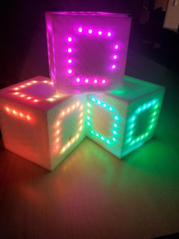
This new take on the classic Simon Says game utilized a motion processing unit and the six faces of a cube to create the game. A round in the game consists of the device lighting up on each side of a cube in a randomized sequence, after which the player must rotate the cube around matching the sequences. If the player manages to follow the correct sequence, then all sides are lit up, and the round ends with golden flashing lights. Additionally, as you win a round, the speed of sequential rounds increases.
Supplies
2. Arduino Nano
3. PLC 3D Printing Material
4. Assorted Wires
5. Soldering Equipment
6. Batterie Pack / AAA batteries
8. Breadboard
9. 2x M3 Bolt
11. MPU-9250
Step 1: Functionality
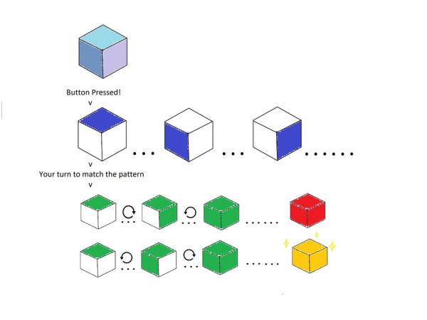
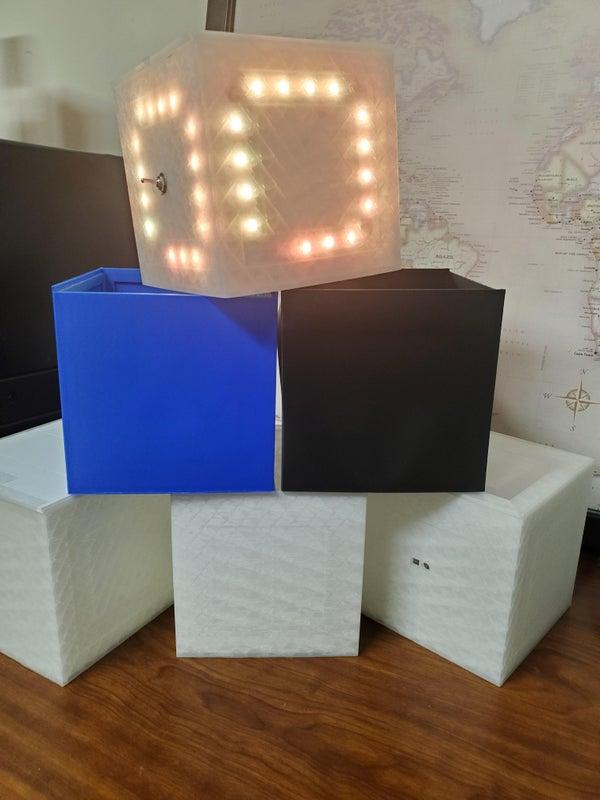
The above image highlights the basic functionality of the cube. In idle, represented at the top of the picture, the cube will softly cycle through a rainbow of colors. Once the button is pressed the game begins and in random order the six faces of the cube will flash blue. Remembering the order the sides were shown, the player now matches the sequence by rotating the respective sides upwards. As a side is rotates upwards, it will flash green indicating a detection and then stay green if correct. If at any point a side is presented to be incorrect to the shown sequence the cube will flash red and the game has been lost. If the player correctly matches the sequence, the cube would now be entirely green and soon followed by flashes of gold indicating a win!
Step 2: Code Logic
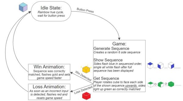
The above diagram further illustrates the functionality of the game and the logic flow the code follows. In the idle state the the cube cycles hues and waits for a detected button press. Once a button press is detected the code generates a random six sides sequence. This rand sequence is then shown to the player via blue lights and then the code waits to get a sequence back from the player. In getting the sequence the code detects which side is facing upwards and matches it the the shown sequence. The code then looks for a loss detected or a win detection as sides are matched. If any incorrect sides are detected it is registered as a loss but if after all six sides are correctly matched a win. Under a win detection the cube will flash gold and the ‘game speed’ at which the sequence will be shown next time is increased. For a loss detection the cube will flash red and any game speed is reset. Under running through a win or loss detection, the cube returns to the idle state to await another button press.
Step 3: Code Snippet
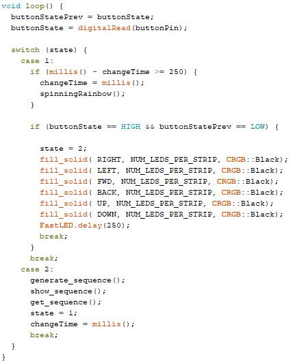
Here we can see the void loop() code that the Arduino is following. The entirety of the code fits nicely into two states, the first being the idle state (case 1) and the second the game (case 2). In case 1 you can see the cube is held in the idle state of spinningRainbow() which aesthetically cycles the cubes color. Along in case 1 it looks to detect a button press and after detecting such switches the state and turns off all the LED’s in preperation for the game. Now in state two the game is divided up into three different void functions, generate_sequence(), show_sequence(), and get_sequence(). Similarly as named, the void function generate_sequence() produces the random sequence for the game to follow, show_sequence() then displays this sequence to the player and get_sequence() utilized the MPU to receive the player inputted sequence.
Step 4: Testing
Throughout this project, we did some initial testing before assembling the whole project. The first thing you should testing while constructing this project is after soldering the six LED matrices is to test them to check all your solder joints are working. After that, we tested various parts.
After printing a box, we realized a few design errors and ended up modifying the box design multiple times until it had all of the features we needed and all of the electrical parts fit in their slots. Once we had the LED matrixes we played with the brightness, wall thickness, and fill pattern of the box to best suit our project, we ended up choosing the cubic infill pattern. Make sure to test your dimension before printing the whole board.
Step 5: 3D Design and Dimensions
Many of the dimensions for this project could be changed depending on how big you want the box to be. The only constants to keep in mind are the sizes of the LED slots. This is a standard for all LED strips. Any 3D printed dimensions can be found in the CAD files.
The dimension for our box as following:
Dimensions:
Length: 5″
Width: 5″
Height: 5″
LED slot width: 0.6″
Screw diameter: 0.11″
The dimension for our lid as following:
Dimensions:
Length: 5″
Width: 5″
Height: 0.164″
LED slot width: 0.6″
Step 6: Circuit Diagram & Power Comsumption
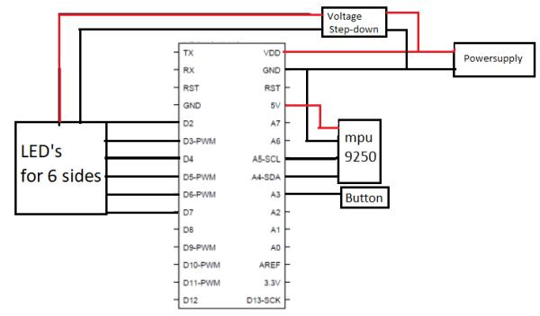
In this basic circuit diagram you can see the setup. The power supply of 6v runs directly to both the Arduino Nano and the stepdown for the LED’s. The voltage is stepped down to ~4v and fed to each of the LED arrays on the 6 faces of the cube. Each of the 6 arrays are connected respectfully to pins 2-7. Back to the Arduino, it supplies the 5v for the MPU-9250 and pins A4 and A5 for data transmission. Lastly the button is pinned to A3.
Power Consumption:
Each LED has a max current draw of 60 mA and using 72 at 4V (17.28 Watts). The Arduino Nano has a max current draw of 19 mA at 5V (.095 Watts) and the MPU-9250 120uA at 3.3V (0.000395 Watts). In total ~17.38 Watts need to be suppled at the 6V from the batterie pack meaning a peak current draw of ~2.9A. Note this is a relatively high current draw for the batteries and would drain them quickly but the LED’s are being ran at a much lower brightness and similarly would be using less than the 60 mA max draw.
Step 7: Assembly
Construction
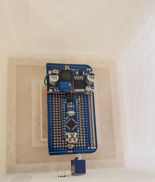
The box was made using a 3D printer with clear PLA filament. All of the lights and wiring connections were soldered. All of the electronics are soldered onto a cookie that is screwed in inside of the box above the battery pack. The LED matrix was soldered together strip by strip and then hot glued into the LED slots inside the box.
After printing out the box and lid, hot glue the LED matrix onto each face of the cube with the LEDs facing out. Now you want to solder together all of the power inputs together then solder a wire from that into the 4 [V] power source. Repeat this step with the LED’s grounds. Connect the LEDs matrix signal inputs into the nano Arduino as right(D2), left(D3), front(D4), back(D5), top(D6) and bottom(D7).
The construction of this project was a lot of fun although there is still room for improvement.
Step 8: Takeaways
Possible Improvements:
-Longer lasting and rechargeable batteries would add a lot of functionality to the cube
-Possibly a second button for different game/color selection could be done
Skills Learnt:
-Completing this project developed many practical and fundamental skills. Practical skills of 3D-printing, wiring and code where all developed along with fundamental skills in the importance of planning and design.
Source: IMU Controlled LED Cube (Simon Says)