Summary of Ultrasonic Tape Measure using Arduino
This article details a DIY ultrasonic tape measure project using an Arduino Duemilanove 2009, an HC-SR04 sensor, and an LCD Keypad. The author modifies the hardware by straightening sensor pins and soldering headers to the keypad for power and signal connections. Software involves custom libraries to calculate distance with high resolution, though the original code is incompatible with newer Arduino environments.
Parts used in the Ultrasonic Tape Measure:
- Arduino Duemilanove 2009
- HC-SR04 Ultrasonic Sensor
- LCD Keypad (Arduino)
- Male header pins
- Electrical tape
- Red nail polish
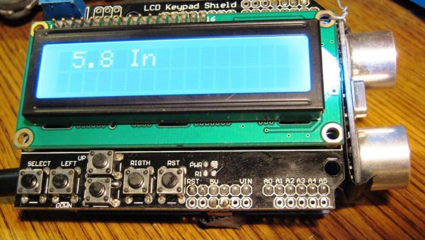
Have you ever wanted an ultrasonic tape measure, like this Stanley? (See picture). Well, I have but then I am a Lazy Old Geek. I don’t really need one but I thought I’d try to make one. And naturally, I thought of an Arduino.
August 2012 update: I just found out the software used in this Instructable does not work in the latest Arduino environment, 1.0. I think it is the LCDKeypad library but haven’t found an updated version or software fix. However, this does work with version 023. LOG
Step 1: Parts List
Arduino $17.60 (Duemilanove 2009) ebay.com
HC-SR04 Ultrasonic $ 4.61 ebay.com
LCD Keypad (Arduino) $ 8.88 ebay.com
Now I realize this is about $30 where the Stanley is available for around $24 but these parts are not committed to one function like the Stanley is.
Parts selection:
I wanted an Arduino that was shield compatible. I already have two, a Freeduino and Seeduino so I decided to buy a third. Right now, one of the best deals I liked is for a standard Arduino Duemilanove 2009 on ebay.
By the way, mine came with an Atmega 328-PU instead of the ‘standard’ Atmega328P-PU. I discussed this in another Instructable:
http://www.instructables.com/id/My-Arduino-Bootloader/
The LCD keypad also has Arduino support plus five user pushbuttons and a 16×2 (16 characters x two rows) display.
Step 2: Mechanical Design
First: I checked the Arduino pins used by the LCD Keypad. They are A0, D4, D5, D6, D7 and D8.
I’d already tested the HC-SR04. I’d set it up to use D2 and D3 and it needs 5V and Ground. So there would be no pin conflicts.
Modification1: The HC-SR04 had male right angle header pins coming out of the bottom of the module. To save room, I wanted them to come straight out of the PCB.
One way: So what I did was unsoldered the four pin connector, removed it and replaced it with straight male pins. (See picture) I also put some electrical tape on the back of the PCB to hopefully prevent it from shorting out.
Better way: That was a hard way to do it. I think a better way would be to take some pliers and carefully straighten the pins. They would be too long but could be cut off.
Second: Tthe LCD keypad is a standard shield and fits right onto a shield-compatible Arduino. The problem is how to connect the HC-SR04 to the system. I didn’t want to solder it directly to the shield or the Arduino.
Well, the LCD keypad has a nice feature. It has the standard male header shield connectors but it also has some extra 0.1” solder pads outside of the shield connectors but connected to the shield pins. (See picture)
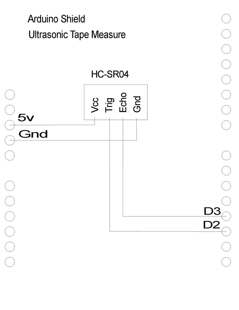
This is the schematic for the HC-SR04 wiring that I used. (See picture)
Modification2: On the bottom of the LCD Keypad, I soldered two male header pins for 5Vdc and GND, so that they pointed downward. (See picture) This was so the connectors and wires would be out of the way for viewing the LCD.
On the top side, I soldered three male header pins on D1, D2 and D3. I used three pins so that it was easier to distinguish the two connectors though I only connected wires to D2 and D3.
TIP: If I was thinking ahead, I would probably have soldered complete six and eight pin male header strips. These might be useful for future projects.
Since it is easy to flip connectors, I used some red nail polish to mark one side of each connector and header.
Step 3: Software design
The LCD keypad and HC-SR04 each have Arduino libraries that have to be added to your Arduino software. Attached
The HC-SR04 libraries had some functions that would print out measurements in inches but I wanted a little better resolution so I wrote my own.
Technical stuff:
Theory of Operation: Basically, the user sends a trigger pulse to the module which sends out an ultrasonic wave. After a period of time the receiver gets back a reflection. The duration determines the distance. The documentation gives a little formula to find distance.
HC-SR04 Ultrasonic
LCD Keypad (Arduino)
For more detail: Ultrasonic Tape Measure using Arduino
- Can this project work with the latest Arduino environment?
No, the software does not work in version 1.0 or later; it only works with version 023. - What are the specific Arduino pins used by the LCD Keypad?
The pins used are A0, D4, D5, D6, D7, and D8. - How can I modify the HC-SR04 pins to save space?
You can unsolder the four-pin connector and replace it with straight male pins, or carefully straighten the existing pins with pliers. - Why did the author use red nail polish on the connectors?
It was used to mark one side of each connector and header to make flipping them easier to avoid. - Does the HC-SR04 require a specific voltage supply?
Yes, the module needs 5V and Ground connections. - What is the theory of operation for the distance measurement?
The user sends a trigger pulse to emit an ultrasonic wave, and the duration until the receiver gets back a reflection determines the distance. - Why did the author write their own library functions instead of using the built-in ones?
The built-in functions printed measurements in inches, but the author wanted better resolution. - What is a suggested improvement for future projects regarding headers?
Soldering complete six and eight pin male header strips would be useful for future projects.