Summary of Ultimate Control: NRF 24L01 Remote for RC Cars and Planes
This project builds an NRF24L01-based wireless remote for RC cars using Arduino Nano, a joystick, push buttons, and transceiver modules. The transmitter reads joystick axes and button states, sends single-character commands via NRF to a receiver Arduino that drives LEDs or motor control pins. The guide includes circuit connections, component list, and transmitter/receiver code using the RF24 library. It emphasizes 3.3V supply, SPI pin wiring, pairing behavior, and the module's long range and low power characteristics.
Parts used in the NRF Remote Control for RC Car:
- NRF24L01 module (with antenna option)
- Arduino Nano
- Joystick module
- Push buttons
- Zero PCB
- Wires
- LEDs (for receiver indicator/output)
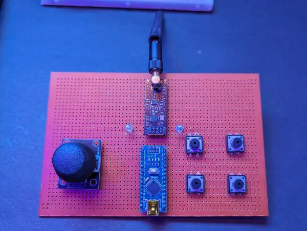
Hello, welcome back to Techatronic, fellow enthusiasts. Today, we’re excited to showcase our latest project: the NRF Remote Control designed specifically for RC cars. This innovative remote is capable of controlling various car models. Additionally, it requires an accompanying device installed within the car or the respective unit to be controlled remotely. The remote control system comprises a transceiver and a controller, effectively managing the remote’s functionalities.
Introduction
This RC remote control utilizes the NRF24L01 module, responsible for enabling wireless communication, as depicted in the accompanying images. The remote automatically pairs with the receiver device. Upon pressing any key or joystick module, it transmits the corresponding information. Previously, we engineered a gesture-controlled robot employing the Bluetooth HC-05 master-slave communication system. In this project, we follow a similar process, but we’ve incorporated the NRF module instead.
The communication range of this module is impressive, reaching nearly 100 meters. This capability is the primary reason for choosing the NRF 24L01 module for this RC Car remote control. Comprehensive guidance on interfacing the NRF module with Arduino, including coding and circuitry, will be provided here to enable you to recreate this exceptional project by following the provided instructions.
Below is the list of components utilized in this project.
Components Required:-
- NRF24L01 with antenna
- Arduino nano
- Joystick module
- Zero PCB
- push button
- wires
The NRF24L01 module serves as a wireless communication module with an extensive range. This versatile module supports 125 distinct channels, facilitating seamless connections among various modules. Each channel can accommodate up to 6 units for communication purposes.
Remarkably, this module boasts remarkably low power consumption, operating at a mere 10 mA during transmission. To put it into perspective, this consumption is notably lower than that of a standard LED.
However, caution is necessary during connections, as exceeding the maximum required voltage of 3.3V can result in module burnout. Notably, there’s no indicator LED to signal its operational status. We’ve integrated this module into our NRF remote control system for its superior communication capabilities and minimal power consumption.
The module interfaces via SPI pins, including MOSI, MISO, SCK, CE, and CSN, connecting these to corresponding pins on the Arduino or the controller in use.
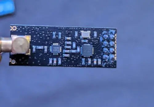
There are two variations available for the NRF module: the standard NRF24L01 module and another equipped with a long-range antenna capable of communication within a 500-meter range. The long-range variation features the RFX2401C chip, housing both a Power Amplifier (PA) and a Low-Noise Amplifier (LNA) in addition to the duck antenna.
Our project involves connecting this module to an Arduino Nano for transmitting data from the transmitter to the receiver.
Previously, we successfully interfaced the joystick module with the Arduino, and you can find comprehensive information about it in the provided link.
For the completion of our project, we now require the circuit diagram.
NRF Remote Circuit Diagram Transmitter
![]()
The circuit diagram provided here offers a clear depiction of the connections required. The vertical and horizontal pins of the joystick should be linked to the A0 and A1 pins, respectively, while the push button needs to be connected to the digital input pins. As for the NRF24L01 module, it should be connected according to the specifications for SPI communication.
Connection Table
| Arduino nano | Joystick module | NRF 24L01 | Push Button |
| pin 2 | – | – | PUSH BUTTON1 T1 |
| pin3 | – | – | PUSH BUTTON2 T1 |
| pin4 | – | – | PUSH BUTTON3 T1 |
| pin5 | – | – | PUSH BUTTON4 T1 |
| pin7 | – | CE | – |
| pin8 | – | CSE | – |
| pin11 | – | MOSI | – |
| pin12 | – | MISO | – |
| pin13 | – | SCK | – |
| A0 | V1 | — | – |
| A1 | H1 | – | – |
| VCC | VCC | – | – |
| GND | GND | GND | PB1 T2, PB2 T2, PB3 T3, PB4 T4 |
| 3V3 | – | VCC | – |
NRF Remote control Circuit Diagram Receeiver
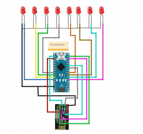
Here the same connection for nrf and arduino and LEDs connect directly to the Arduino nano.
Connection Table
| Arduino nano | LEDs | NRF24L01 |
| A7 | L1 ANODE | – |
| A6 | L2 ANODE | – |
| A5 | L3 ANODE | – |
| A4 | L4 ANODE | – |
| 13 | – | SCK |
| 12 | – | MISO |
| 11 | – | MOSI |
| 8 | – | CSE |
| 7 | CE | |
| 5 | L5 ANODE | – |
| 4 | L6 ANODE | – |
| 3 | L7 ANODE | – |
| 2 | L8 ANODE | – |
| VCC | – | – |
| GND | ALL CATHODE | GND |
| 3V3 | – | VCC |
NRF Remote Control for RC Car code for transmitter
//Library: TMRh20/RF24, https://github.com/tmrh20/RF24/
#include
#include
#include
RF24 radio(7, 8); // CE, CSN
const byte address[6] = “00001”;
void setup() {
Serial.begin(9600);
radio.begin();
radio.openWritingPipe(address);
radio.setPALevel(RF24_PA_MIN);
radio.stopListening();
pinMode(2, INPUT_PULLUP);
pinMode(3, INPUT_PULLUP);
pinMode(4, INPUT_PULLUP);
pinMode(5, INPUT_PULLUP);
pinMode(A0, INPUT_PULLUP);
pinMode(A1, INPUT_PULLUP);
}
void loop() {
int m = digitalRead(2);
int n = digitalRead(3);
int o= digitalRead(4);
int p = digitalRead(5);
int q = analogRead(A0);
int r = analogRead(A1);
Serial.print(m);
Serial.print(” “);
Serial.print(n);
Serial.print(” “);
Serial.print(o);
Serial.print(” “);
Serial.print(p);
Serial.print(” “);
Serial.print(q);
Serial.print(” “);
Serial.println(r);
if(m==0)
{
const char text[] = “A”;
radio.write(&text, sizeof(text));
delay(100);
}
else if(n==0)
{
const char text[] = “B”;
radio.write(&text, sizeof(text));
delay(100);
}
else if(o==0)
{
const char text[] = “C”;
radio.write(&text, sizeof(text));
delay(100);
}
else if(p==0)
{
const char text[] = “D”;
radio.write(&text, sizeof(text));
delay(100);
}
else if(q>=1000)
{
const char text[] = “E”;
radio.write(&text, sizeof(text));
delay(100);
}
else if(q<20)
{
const char text[] = “F”;
radio.write(&text, sizeof(text));
delay(100);
}
else if(r<20) { const char text[] = “G”; radio.write(&text, sizeof(text)); delay(100); } else if(r>1000)
{
const char text[] = “H”;
radio.write(&text, sizeof(text));
delay(100);
}
else
{
const char text[] = “nothing”;
radio.write(&text, sizeof(text));
delay(100);
}
}
here we using the terms in code which define the following like
#include <SPI.h>
#include <nRF24L01.h>
#include <RF24.h>
Here we are including the nrf libraries into the front end code from backend.
RF24 radio(7, 8); // CE, CSN

const byte address[6] = "00001";
First line define the pins we are using for ce and ece pin of NRF module.
and the second line define the address of the nrf to communicate with the other nrf module
Serial.begin(9600);
  radio.begin();
  radio.openWritingPipe(address);
  radio.setPALevel(RF24_PA_MIN);
  radio.stopListening();
The initial step initiates serial communication between the Arduino and the computer, primarily utilized to view data on the serial monitor.
Following this, the subsequent step triggers radio communication between the two NRF modules.
Once this communication is established, the data is transmitted at the same frequency, ensuring that the receiver can accurately receive the information.
pinMode(2, INPUT_PULLUP);
   pinMode(3, INPUT_PULLUP);
    pinMode(4, INPUT_PULLUP);
     pinMode(5, INPUT_PULLUP);
     pinMode(A0, INPUT_PULLUP);
     pinMode(A1, INPUT_PULLUP);
These all lines of codes configuring the input pins which will be used by joystick and push buttons.
 if(m==0)

  {

    const char text[] = "A";
  radio.write(&text, sizeof(text));
  delay(100);

    }
there we are using some conditions like if any button press then what will bee send from transmitter to receiver.
NRF Remote Control for RC Car code for Receiver
Certainly, here’s a rephrased version of the provided code:
“`cpp
#include
#include
#include
RF24 radio(7, 8); // CE, CSN
const byte address[6] = “00001”;
void setup() {
Serial.begin(9600);
radio.begin();
radio.openReadingPipe(0, address);
radio.setPALevel(RF24_PA_MIN);
radio.startListening();
pinMode(2, OUTPUT);
pinMode(3, OUTPUT);
pinMode(4, OUTPUT);
pinMode(5, OUTPUT);
pinMode(A3, OUTPUT);
pinMode(A2, OUTPUT);
pinMode(A5, OUTPUT);
pinMode(A4, OUTPUT);
}
void loop() {
if (radio.available()) {
char text[32] = “”;
radio.read(&text, sizeof(text));
Serial.println(text);
if (strcmp(text, “E”) == 0) {
digitalWrite(2, HIGH);
digitalWrite(3, LOW);
digitalWrite(4, HIGH);
digitalWrite(5, LOW);
} else if (strcmp(text, “F”) == 0) {
digitalWrite(2, LOW);
digitalWrite(3, HIGH);
digitalWrite(4, LOW);
digitalWrite(5, HIGH);
} else if (strcmp(text, “H”) == 0) {
digitalWrite(2, LOW);
digitalWrite(3, HIGH);
digitalWrite(4, HIGH);
digitalWrite(5, LOW);
} else if (strcmp(text, “G”) == 0) {
digitalWrite(2, HIGH);
digitalWrite(3, LOW);
digitalWrite(4, LOW);
digitalWrite(5, HIGH);
} else {
digitalWrite(2, LOW);
digitalWrite(3, LOW);
digitalWrite(4, LOW);
digitalWrite(5, LOW);
}
}
}
“`
This code initializes the NRF24L01 module for wireless communication. It sets up the necessary pins and listens for incoming data, responding with specific actions based on the received commands (“E”, “F”, “H”, “G”). The Arduino’s digital output pins 2, 3, 4, and 5 are controlled accordingly based on the received commands.
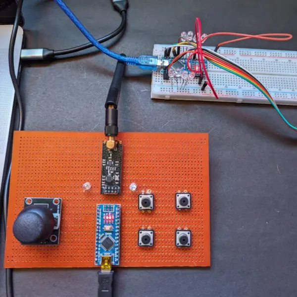
After uploading the both code try to plug the power and observe on thee serial monitor.
Source: Ultimate Control: NRF 24L01 Remote for RC Cars and Planes
- What wireless module is used in this RC remote project?
The NRF24L01 module is used for wireless communication in this project. - Can the NRF24L01 modules automatically pair between transmitter and receiver?
Yes, the remote automatically pairs with the receiver device as described in the article. - What microcontroller is used for the transmitter and receiver?
Both transmitter and receiver use an Arduino Nano. - How are joystick axes connected to the Arduino?
The joystick vertical and horizontal pins are connected to analog pins A0 and A1 respectively. - What voltage must be supplied to the NRF24L01 module?
The NRF24L01 must be powered at 3.3V and exceeding this voltage can burn the module. - Which Arduino pins are used for SPI connections to the NRF24L01?
The SPI pins used are MOSI on pin 11, MISO on pin 12, and SCK on pin 13, with CE on pin 7 and CSN on pin 8 in the provided setup. - What library is required for the NRF24L01 code?
The RF24 library by TMRh20 (nRF24L01) is used as indicated in the code comments. - How does the transmitter send commands when buttons or joystick move?
The transmitter reads button and analog joystick values and writes single-character strings over radio using radio.write based on conditions in loop. - What does the receiver do when it gets command E or F?
Upon receiving E or F, the receiver sets specific digital output pins HIGH or LOW to reflect forward or backward control as shown in the code. - What power characteristic of the NRF24L01 is highlighted?
The module has very low power consumption, about 10 mA during transmission, noted as lower than a typical LED.