This project was created by Daniel Månsson [], Flemming Andersen [flem781a] and Mikkel Pavia [mikk24b9] as an exam project at the school University College Lillebælt.
As a part of one of our electives, during second semester, in automation engineering, we were tasked with creating an Arduino project.
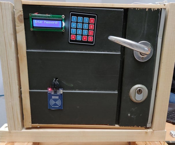
As a student at our school, you get an RFID chip to allow you access to certain areas of the school as well as entrance to the school after opening hours – we wanted to create an add-on for existing door locks at home. The door lock will feature a keypad, an RFID reader, Bluetooth connectivity and a display.
The parts needed for attaching the servo to the deadbolt on the door were printed using a Ultimax 2+ 3D printer.
Step 1: Components
Here are the components we used for our setup, you can probably mix/match various models.
The following components can be purchased from various sellers, such as Aliexpress or eBay.
The components we used to success are as following:
- Arduino MEGA (2560R3)
- Servo (MG996R)
- SD-card module (No model no.)
- Real time Clock (DS3231)
- Bluetooth (hc-05)
- RFID (RC522)
- Keypad 4*4 (membrane matrix)
- LCD 16*2 (1602A)
- RFID Tag
- SD
- Resistor (2k and 220)
- Led (Green, Red)
- Switch
- Potentiometer
- SD card fitting the module
- Android Phone
A more complete list with both amounts, model and a links to a danish vendor is attached.
Step 2: How It Should Work
When first connected to power the door lock starts out by locking, then sits ‘idle’, awaiting any user input.
Keypad
If the keypad is pressed, it starts checking up the pressed key against the stored password.
If a wrong key is pressed it increases the wrong counter.
When 4 digits have been pressed, it will check the wrong counter, if above ‘0’ the LCD prints “Wrong Password” and the lock will stay locked.
If 4 digits have been pressed and the wrong counter is ‘0’ the LCD prints “Password Accepted” and the lock unlocks.
if however pressing ‘#’ or ‘*’ during any of this it will reset the process & counter values.
Bluetooth
If Bluetooth data is received, it reads the received data – if this data is ‘1’ the lock unlocks, it also sends back “Unlocked” to the Bluetooth device(Android Phone)
RFID
The RFID module scans if there is any readable tags nearby, if there isn’t it simply skips over. If there is a readable tag nearby – it reads the tags value and matches it up against our predefined tags, if it doesn’t match it simply prints “Not Authorized” on the LCD. If the tag matches up, it prints “Welcome ” and unlocks the door. It will also save the date and time including the tag holder’s name to a text file on the SD card.
Unlocked
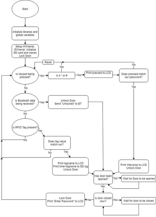
When the lock unlocks, it sets a step, this is used to check when the door opens/closes so the lock will engage again. It basically uses 3 steps to keep track of where it is, the operation is done with a simple switch currently.
Successfully unlocking will also lit a green led, just like a red led will be lit if it is currently locked.
We’ve attached a flowchart above that simplifies this.
Step 3: Wiring and Electrical Component Setup
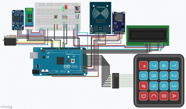
We’ve made use of the Fritzing software to sketch up our wiring.
To make the Fritzing schematic easier to do, we also made up an IO/Arduino mega pin list – both of these are also included in our files.
In the electrical diagram above, you will find every necessary connection between the components including an overview of the wiring.
Since we’re using quite a few wires and the double row at the bottom of the Arduino the wire points can be quite hard to see with this quality, we recommend downloading the picture and zooming in.
As you can see we’re wiring only a few things to the breadboard, mostly power(5 V) and GND, this however doesn’t reflect our real world test setup where we used the breadboard for holding most of the modules excluding SD Card and the keypad, this will also be shown in a later step.
Also do note that we’re using a potentiometer to control the brightness of the LCD.
listing the ‘larger’ objects/modules from left to right: Servo, DS3231, HC-05, Breadboard+Arduino, RC522, SD card, LCD, Keypad.
In the Diagram above + leading wires are red for 5 V, brown for 3.3 V, -(GND) leading wires are blue.
Step 4: Programming the Arduino
So programming the Arduino itself – this is where the fun begins – we’ve attached 5 pictures above with different sections of the code. This is the code from our testing setup where we had a lot of troubleshooting serial prints in the code, they were a great help to see where we got stuck/what we did wrong.
The code has been compressed a bit to fit the pictures better.
The first picture above is what we’re initializing and global variables:
Lines below:
1 initializing the software serial, including setting the pins so we don’t have to use the HW serial.
4 initializing the real time clock module
7-9 defining pins including slave select pin for RFID module, and creating the instance.
12-13 defining the slave select pin for our SD card module, also setting the file variable
16-28 defining(mapping) the layout of the keypad, rows and columns, also setting the pins used.
31 defining the pins used for the LCD.
33-37 declaring the variables.
40 defining the servo motor.
43 our string variable containing the default password.
44-45 variables for LCD position and keypad presses.
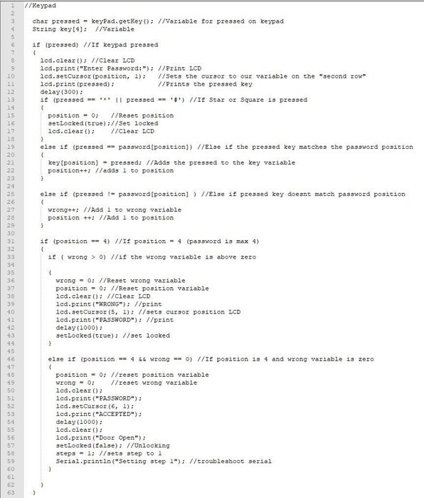
The second picture above is programming the keypad:
3-4 are the variables used to track what is pressed on the keypad and also the ‘key’ password.
6-12 are printing the key pressed to the LCD, the delay makes the code wait a few seconds before the key pressed disappears on the LCD.
13-18 are simply what should happen if the ‘*’ or ‘#’ is pressed – in our case its a reset.
19-23 what happens if the pressed key matches our predefined password.
25-29 if the pressed key does not match our predefined password.
31-44 what happens if we reached the max length of our password (4 digits) and we’ve had wrong key presses.46-60 and at last if we’ve reached max length and there have been no wrong inputs
The third picture above is programming the Bluetooth:
2 here we check if there is any data coming from the Bluetooth on the serial port.
3 Since we’re only handling a simple ‘1’ from the Bluetooth the code here reads from the serial and puts it in our variable.
4-8 what happens if there was a ‘1’ coming from the Bluetooth connection, here we also send back “Unlocked” to the Bluetooth serial.
The fourth picture above is programming the RFID:
4-5 we’re checking if there is a card nearby.
8-9 reading the value from the card.
12-18 adding the RFID value to our string variable.
20-21 basically making the content of our variable uppercase.
22 we’re checking if the variable matches our predefined.
24-25 selecting our slave, we need the SD card module.
27 we’re opening the file on the SD card so its ready to receive printed data.
29-69 if our variable data matches either of our predefined, we print name on the LCD, and print both date&time and the name to our log on the SD card.
70-72 calling the function “setlocked” and setting it false – unlocking the lock.
74-78 if the tag value didn’t match our predefined.
Fifth picture above is our function actually controlling the servo:
3 if setLocked(true) is called.
5-10 attaching the servo and giving it a position to go to, basically locking the door.
12 if setLocked(false) is called
13-20 attach the servo and give it a position to go to, unlocking the door.
Step 5: Programming the Android Phone
We’ve made use of the simple to use web based MIT App Inventor 2 for programming the Android phone.
Not having used App Inventor before, we found it pretty simple and straight forward to use – since its made like a puzzle. We did however follow various guides for basic functionality.
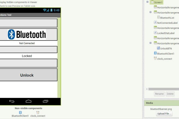
First picture is how our simple app ended up looking – as you can see on the right side there are two buttons, one of them being a list.
Clicking the Bluetooth banner at the top reveals a Bluetooth list for the phone, tapping HC-05 will connect your phone to the Arduino Bluetooth module.
Then there’s the unlock button – it does what it says, unlocks the door, we’ve got no way of locking the door, since if you open it, it’ll auto lock when closing.
The first line of text simply shows if you’re connected or not – in the actual app this is either red or blue depending on connection.
The second shows the current state of the lock.
The second picture is our block design(puzzle) – what the app actually does.
Starting from the top left we’re basically telling it what to do when the Bluetooth banner is clicked.
Second part is that we’re wanting to connect to the selected device in the popup.
Third part is what we want to do when clicking the unlock button – we’re simply sending 49, and since this is sent with ASCII the number ’49’ equals ‘1’ – so we’re actually sending a ‘1’ to the Arduino.
Moving on to the right side of the picture we’re using a clock timer to update (somewhat real time) the connection text, so if the connection is dropped so will the text show.
We’re also using this clock to send out our locked/unlocked status, this does have a downside of throwing a “no connected Bluetooth device” when starting the app up, but we’d prefer this over incorrect status.
Step 6: 3D Printing
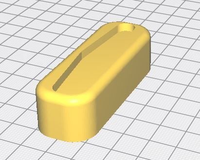
As explained earlier we made use of some 3D printed parts for attaching the servo to the deadbolt.
The printer we had access to was an Ultimaker 2+, using 0.4 mm black PLA.
The software we used was Fusion 360 to edit the designs and Cura to make it suitable for the Ultimaker.
It is pretty simple, consisting of two things, one being the deadlock attachment, and the second being the mount for the servo – there is included a hole for for an led and also if wanted, a square hole for a button for manual operation.
The deadbolt attachment took just over three hours to print, the servo mount/housing took just over 21 hours to print.
Credits to Hacker Shack for the 3D design for the deadbolt
and a link to his: https://bit.ly/2YQ4c97
Step 7: Testing Setup
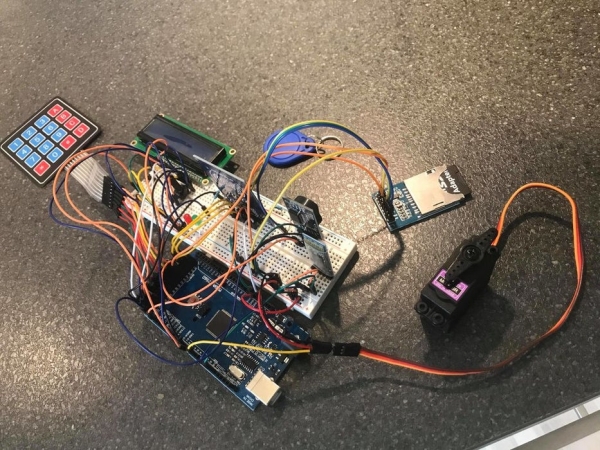
Since we were all sort of new to programming Arduino – and just cause it is a good idea to test things out first before soldering everything together and possibly putting it in a nice box, we’ve made use of the large breadboard for attaching most things together. This does however make it quite messy to look at with all the wiring.
After making sure that everything was working as we wanted, all there was left is fitting the servo to the 3D printer adapter and attaching the servo to the housing using screws.
You might have to use spacers to make it fit your deadbolt.
Since this was a project in our semester, we didn’t actually solder things together since we’d like to use our parts for different projects later – it would however have made it much better looking, being able to remove a lot of the wiring.
Step 8: Testing Setup – Youtube
Step 9: Full Code
<p>//Libraries used<br>#include <LiquidCrystal.h> //LCD MODULE<br>#include <Keypad.h> //Keypad MODULE<br>#include< MFRC522.h> //RFID MODULE<br>#include <SPI.h> //RFID AND SD CARD MODULES<br>#include <SD.h> //SD CARD MODULE<br>#include <DS3231.h> //RTC MODULE<br>#include <Servo> //Servo MODULE<br>#include <SoftwareSerial.h> //Software Serial</p><p>SoftwareSerial mySerial(10, 11); //SoftSerial initialize. pin number RX, TX</p><p>//Realtime clock hardware interface initialize
DS3231  rtc(SDA, SCL);</p><p>//RFID pins same instance
#define SSRFID_PIN 53 //SS PIN for RFID   //SS PIN (Slave Select)
#define RSTRFID_PIN 47                    //RST PIN
MFRC522 mfrc522(SSRFID_PIN, RSTRFID_PIN); //instance</p><p>//SD Card
#define SSSD_PIN 54 //SS PIN (Slave Select)
File myFile;        //File being used</p><p>//KEYPAD Grid
const byte ROWS = 4; //keypad Rows
const byte COLS = 4; //keypad Columns
//layout af keypad
char hexaKeys[ROWS][COLS] = {
  {'1', '2', '3', 'A'},
  {'4', '5', '6', 'B'},
  {'7', '8', '9', 'C'},
  {'*', '0', '#', 'D'}
};
byte rowPins[ROWS] = {31, 33, 35, 37}; //pinout Rows
byte colPins[COLS] = {39, 41, 43, 45}; //pinout Columns</p><p>Keypad keyPad = Keypad( makeKeymap(hexaKeys), rowPins, colPins, ROWS, COLS);</p><p>//LCD RELATED
LiquidCrystal lcd(22, 23, 24, 25, 26, 27); //LCD pins</p><p>int redPin = 2;   //Red LED Pin (No Access)
int greenPin = 3; //Green LED Pin (Access Granted)
int doorPin = 5;  //Door Magnet (HIGH if door is closed)
int steps = 0;    //Step counter for door + locking control
int state = 0;    //Bluetooth state</p><p>//Servo (needed in setlocked function)
Servo servo_Motor;</p><p>String password = "1234"; //Keypad Default Password
int position = 0; // Variable for Cursor(LCD) and Password position(0-3  = 4)
int wrong = 0; // Variabel for wrong password</p><p>//RFID
//1A 83 57 D3 = Blue RFID Tag
//52 0B C6 1F = White Creditcard Tag</p><p>void setup() {
  Serial.begin(9600); //Start the Serial Function(to communicate over USB)
  rtc.begin();        //Start the Real Time Clock</p><p>  mySerial.begin(9600); //Bluetooth Serial</p><p>  pinMode(doorPin, INPUT_PULLUP);</p><p>  //SD CARD
  pinMode(46, OUTPUT);  //Changes pin 46 to output mode (SS pin)
  digitalWrite(46, HIGH); //Has to be high from startup since we're using RFID</p><p>  //RFID
  pinMode(53, OUTPUT);  //Changes pin 53 to output mode (SS pin)
  digitalWrite(53, LOW); //Has to be low from startup so RFID is used.
  SPI.begin();          //Start the SPI (Serial Peripheral Interface) for RFID&SDCard
  mfrc522.PCD_Init();   //Start the RFID</p><p>  if (!SD.begin(46)) {                     //Start the SD library and Card (! for invert)
    while (1);
  }
  Serial.println("initialization done."); //Troubleshoot Serial</p><p>  lcd.begin(16, 2); //LCD Size
  lcd.clear();
  servo_Motor.attach(6); //Attach Servo to pin 6(PWM)
  setLocked(true); //Locks the first time during setup
}</p><p>void loop() {</p><p>  lcd.clear(); //Clears the LCD
  lcd.print("Enter Password:"); //Prints on the LCD
  delay(100);</p><p>  //Keypad</p><p>  char pressed = keyPad.getKey(); //Variable for pressed on keypad
  String key[4];  //Variable</p><p>  if (pressed) //If keypad pressed
  {
    lcd.clear(); //Clear LCD
    lcd.print("Enter Password:"); //Print LCD
    lcd.setCursor(position, 1);   //Sets the cursor to our variable on the "second row"
    lcd.print(pressed);           //Prints the pressed key
    delay(200);
    if (pressed == '*' || pressed == '#') //If Star or Square is pressed
    {
      position = 0;   //Reset position
      setLocked(true);//Set locked
      lcd.clear();    //Clear LCD
    }
    else if (pressed == password[position]) //Else if the pressed key matches the password position
    {
      key[position] = pressed; //Adds the pressed to the key variable
      position++; //adds 1 to position
    }</p><p>    else if (pressed != password[position] ) //Else if pressed key doesnt match password position
    {
      wrong++; //Add 1 to wrong variable
      position ++; //Add 1 to position
    }</p><p>    if (position == 4) //If position = 4 (password is max 4)
    {
      if ( wrong > 0) //if the wrong variable is above zero</p><p>      {
        wrong = 0; //Reset wrong variable
        position = 0; //Reset position variable
        lcd.clear(); //Clear LCD
        lcd.print("WRONG"); //print
        lcd.setCursor(5, 1); //sets cursor position LCD
        lcd.print("PASSWORD"); //print
        delay(1000);
        setLocked(true); //set locked
      }</p><p>      else if (position == 4 && wrong == 0) //If position is 4 and wrong variable is zero
      {
        position = 0; //reset position variable
        wrong = 0;    //reset wrong variable
        lcd.clear();
        lcd.print("PASSWORD");
        lcd.setCursor(6, 1);
        lcd.print("ACCEPTED");
        delay(1000);
        lcd.clear();
        lcd.print("Door Open");
        setLocked(false); //Unlocking
        steps = 1; //sets step to 1
      }</p><p>    }
  }
  //Bluetooth
  else if (mySerial.available() > 0) { // Checks whether data is comming from the serial port
    state = mySerial.read(); // Reads the data from the serial port
    if (state == '1') {
      lcd.clear();    //Clear LCD
      lcd.print("Bluetooth Open"); //LCD print
      setLocked(false); //unlocking
      steps = 1; //sets steps so door autolock works
      mySerial.println("Unlocked"); // Send back the String "Unlocked"
    }
  }</p><p>  //RFID</p><p>  else {
    //Wait for a card
    if ( ! mfrc522.PICC_IsNewCardPresent()) {
      return;
    }
    //Read Card value
    if ( ! mfrc522.PICC_ReadCardSerial()) {
      return;
    }</p><p>    String content = "";    //Variable for UID from tag
    for (byte i = 0; i < mfrc522.uid.size; i++) {
      content.concat(String(mfrc522.uid.uidByte[i] < 0x10 ? " 0" : " "));
      content.concat(String(mfrc522.uid.uidByte[i], HEX));
    }</p><p>    //Compare RFID Tags and do XX</p><p>    content.toUpperCase();
    content = content.substring(1);
    if ((content == "1A 83 57 D3") || (content == "52 0B C6 1F")) { //If variable content matches either tag</p><p>      digitalWrite(53, HIGH); //SS Pin RFID HIGH to not use
      digitalWrite(46, LOW);  //SS pin SD Card LOW to use</p><p>      myFile = SD.open("log.txt", FILE_WRITE); //Opens the file on SDCARD</p><p>      if (content == "1A 83 57 D3") { //If variable matches
        lcd.clear();
        lcd.setCursor(3, 0);
        lcd.print("Velkommen"); //Print welcome LCD
        lcd.setCursor(4, 1);
        lcd.print("Flemming"); //print name LCD
        //SD START
        myFile.print(rtc.getDateStr()); //Prints the RTC Date to SD card
        myFile.print(" ");              //Prints a space
        myFile.print(rtc.getTimeStr()); //Prints RTC Time HH/MM/SS
        myFile.print(" ");              //Prints a space
        myFile.println("Flemming");     //Prints the name entering
        myFile.close();                 //Closes the file opened on the SD Card
        digitalWrite(46, HIGH); //SS pin SD card High
        digitalWrite(53, LOW);  //SS pin RFID Low
      }
      if (content == "52 0B C6 1F") {
        lcd.clear();
        lcd.setCursor(3, 0);
        lcd.print("Velkommen");
        lcd.setCursor(4, 1);
        lcd.print("Mikkel");
        myFile.print(rtc.getDateStr()); //Prints the RTC Date to SD card
        myFile.print(" ");              //Prints a space
        myFile.print(rtc.getTimeStr()); //Prints RTC Time HH/MM/SS
        myFile.print(" ");              //Prints a space
        myFile.println("Mikkel");     //Prints the name entering
        myFile.close();                 //Closes the file opened on the SD Card
        digitalWrite(46, HIGH); //SS pin SD card High
        digitalWrite(53, LOW);  //SS pin RFID Low
      }
      setLocked(false);  //Unlocking
      steps = 1; //Setting step 1</p><p>    }
    else { //If RFID Tag doesnt match
      lcd.clear();                 //Clear LCD
      lcd.print("Not Authorized"); //Print LCD
      delay(2000);
    }
  }</p><p>  //Door Magnet, closed, open, closed (For relocking)</p><p>  while (steps > 0) { //If steps is above 0
    if ((steps == 1) && (digitalRead(doorPin) == HIGH )) {  //If step = 1 read the doorpin if high (closed) continue
      steps = 2;  //Set step 2
    }
    if ((steps == 2) && (digitalRead(doorPin) == LOW)) { //if step = 2 read the doorpin if low (open)
      steps = 3; //set step 3
    }
    if ((steps == 3) && (digitalRead(doorPin) == HIGH)) { //If step = 3 read the doorpin if high (closed) continue
      setLocked(true); //set locked
      lcd.clear();     //Clear LCD
      lcd.print("Enter Password:"); //LCD print
      mySerial.println("locked"); // Send back the String "locked"
      steps = 0;       //set steps = 0
    }
  }
} //loop end</p><p>void setLocked(int locked)  //function for the doorlock
{
  if (locked) //if locked is true, lock
  {
    digitalWrite(redPin, HIGH); //Red on
    digitalWrite(greenPin, LOW); //Green off
    servo_Motor.attach(6); //attach servo to pin 6
    servo_Motor.write(150); //write Servo position
    delay(1000);
    servo_Motor.detach(); //deattach servo
  }
  else //if locked is false, unlock
  {
    digitalWrite(redPin, LOW); //Red off
    digitalWrite(greenPin, HIGH); //Green on
    servo_Motor.attach(6); //Attach Servo to pin 6
    servo_Motor.write(0); //write servo position
    delay(1000);
    servo_Motor.detach(); //Deattach Servo
  }
}</p>
Step 10: Final Thoughts
This turned out to be a fun little project for our second semester in automation.
The upside:
Fun and functional project, we’ve got to try out things like building a simple app using MIT App Inventor 2 and using the Ultimaker 3D printers, also fiddling around with all the wires on the breadboard, making the code actually work – it did give some insight to how text based programming works.
The downside:
Possibly not the most secure (there is none) smart lock – also that it doesn’t leave the smallest of footprints – even the Arduino and breadboard is quite large.
Possible future upgrades:
Changes to the 3D design, both to make it leave less of a footprint and also to make room for the Arduino – this could include using a cogwheel function so the servo can sit on the side along with the Arduino.
Also soldering things together as said earlier, the wires are quite messy.
Adding some sort of security, to make it actually suitable for a front door.
Final comments:
Looking back at the project it did turn out great – so overall we are very satisfied with our results with the amount of time we were given.
Source: UCL-Embedded – Arduino Door Lock