Summary of How to Transmit Mouse Data Using Xbee with Arduino
This project demonstrates transmitting PS2 mouse data wirelessly to a PC using an Arduino Pro Mini and Xbee modules. The system reads movement coordinates and button status via the PS2 protocol, processes them on the microcontroller, and sends the data over a ZigBee network. A USB-to-TTL converter is used for programming and serial debugging.
Parts used in the Wireless PS2 Mouse Data Transmission Project:
- Arduino Pro Mini board
- Xbee S1 series transceiver modules (two units)
- PS2 mouse with 6 pin mini DIN connector
- USB to TTL converter board
- Custom PS2 library file (PS2Mouse.h)
- Breadboard compatible design boards for Xbee modules
The PS2 mouse is an input device which can communicate with a host device using the PS2 protocol. It can be connected to a host device using the 6 pin mini DIN connector. The mouse will continuously give output which can be decoded to get the movement in the X-Y plane and also the status of the buttons on the mouse.
The data read from the mouse can be decoded and processed to get the amount of change in position of the mouse with respect to the position at the previous read. This data is normally used in PCs to move a pointer in the screen. The PS2 protocol is a simple two wire synchronous protocol which makes it possible for the simple microcontroller board to interface the standard PS2 mouse or keyboard with it.
 This particular project demonstrates how to transmit the data read from a standard PS2 mouse from a microcontroller board to a distant PC. The microcontroller board used in this project is the easy prototyping hardware platform Arduino and the wireless transmission system is implemented using Xbee transceiver modules.
The Xbee is the brand name wireless transceiver device which works on the ZigBee protocol. The ZigBee is the name of a wireless protocol maintained by the IEEE 802.15 standard. This protocol is specified for wireless Personal Area Network (PAN) using low powered wireless transceivers. They can be used for simple point to point communication systems also.
In this project the Arduino pro-mini board is used which is pre-programmed with the Arduino boot-loader.The programming IDE used for this project is Arduino IDE version 1.0.3 on windows operating system. The image of the Arduino pro-mini board and the Arduino IDE is shown in the following:
Another hardware which can perform the USB to TTL conversion is used to upload the program into the arduino board. This board can be also when it is required to perform serial communication between the PC and the Arduino board.
It is assumed that the reader has gone through the project how to get started with the arduino and done all the things discussed in it.
The PS2 mouse uses a synchronous communication with the PC which is very much similar to the Two Wire Interface protocol. The PS2 connector has a pin for Data and another pin for Clock and using only these two pins the mouse communicate with the host device. The mouse always has 6 pin mini-DIN male connector for PS2 interface and the host device always has the corresponding female pin. The images and the pin-outs of the PS2 male and female connectors are shown in the following image:
The image of the PS2 male pin
When it comes to connecting the female connector with the circuit board one should be able to identify the pins at the bottom of the PS2 connector and the following image will be helpful. The code written for this project uses the custom PS2 library file called “PS2Mouse.h” which has all the necessary routines for accessing a PS2 mouse. There are two functions which the user can directly make use in their code and are namely “mouse.initialize()” and “mouse.report(data)”. The details of the functions are discussed in the following.
mouse.initialize()
The function mouse.initialize() is used to perform all the necessary things to initialize data reporting from a mouse. Once the initialization is done properly the mouse starts sending the data regarding its X-Y movement and the status of the buttons on the mouse. The function takes no parameter and returns nothing but will exist only when the initialization is properly done.
mouse.report(data)
The function mouse.report(data) can be used to read the current data from the mouse. The function should be provided with an integer array of three elements and the function will fill the elements with the required values. The first element is written with the status value, the second element with the X movement value and the third element will be written with the Y movement value.
The method of reading the data from the PS2 mouse using the above functions and decoding them to get the X-Y coordinates are explained in a previous project on how to interface a PS2 mouse with the Arduino.
Two Xbee S1 series transceivers modules are used in this project and the image of the same module shown in the following figure. Since the pitch of the pins of the modules are not breadboard compatible one can use the Xbee based design boards which comes with breadboard compatible pins.
The Xbee modules have several digital and analog I/O pins apart from these pins and the pin out of an Xbee module is shown in the following table:
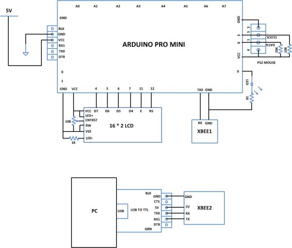
Since the Xbee modules communicate using serial communication protocol with the interfacing devices they can be connected to a microcontroller using a minimum of four pins, Power supply, and Ground, UART Data Out, and UART Data In pins. The pin number 2, UART Data Out is connected to the RX1 pin of the Arduino pro mini board and pin number 3 UART Data In is connected to the TX0 pin.
The implementation of the project which can receive the data from PS2 mouse and transmit the X-Y coordinate extracted from the mouse data through Xbee is represented using the following block diagram:
 The code written for this project on Arduino reads the PS2 mouse data continuously and writes the same data to the Xbee for transmission with the help of serial communication functions provided by the Arduino IDE. The functions like Serial.begin() which helps to initialize the serial port with a given baud rate, Serial.write() to send a data to the serial port, Serial.available() and Serial.read() functions to read data from the serial port are used in this project and they are already discussed in previous projects on how to do serial communication with the Arduino,how to send and receive serial data using arduino and how to do serial debugging with the Arduino. The method of getting the required X-Y data from the PS2 mouse is explained in the previous project on how to interface a PS2 mouse with the Arduino. The method of interfacing an Xbee module and transmission of data using it is discussed in as previous project on how to interface Xbee module with Arduino{C}{C}{C}{C}{C}{C}[H1]{C}{C}{C}{C}{C}{C} {C}{C}{C}{C}{C}{C}{C}{C}{C}{C}{C}{C}.
When the coding is finished one can verify and upload the code to the Arduino board as explained in the project how to get started with the Arduino. As soon as the board is powered up the Xbee in the Arduino board automatically establishes communication with another Xbee which is connected to the serial port of a PC. The second Xbee board can be connected to the PC using the same USB to TTL converter board which has been used to program the Arduino board. The X-Y position can be then be read using any serial monitoring software or using the Arduino IDE’s serial monitoring software itself as explained in the project how to do serial debugging with the Arduino.
For more detail: How to Transmit Mouse Data Using Xbee with Arduino
- How does the PS2 mouse communicate with the host device?
The PS2 mouse uses a simple two-wire synchronous protocol with separate pins for Data and Clock. - What functions are available in the custom PS2 library?
The library provides mouse.initialize() for setup and mouse.report(data) to read status and movement values. - Which wireless protocol do the Xbee modules use?
The Xbee modules operate using the ZigBee protocol maintained by the IEEE 802.15 standard. - Can Xbee modules be connected directly to a breadboard?
No, because their pin pitch is not breadboard compatible, so design boards with compatible pins are required. - How many pins are needed to connect an Xbee module to a microcontroller?
A minimum of four pins is required: Power supply, Ground, UART Data Out, and UART Data In. - What happens when the Arduino board is powered up?
The Xbee automatically establishes communication with another Xbee connected to the PC serial port. - How can the X-Y position data be viewed on the computer?
The position can be read using any serial monitoring software or the Arduino IDE serial monitor. - Which version of the Arduino IDE was used for this project?
The project utilized Arduino IDE version 1.0.3 on the Windows operating system.