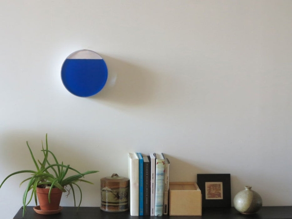
This is a tutorial for making the Tidal Clock. The clock shows the ebb and flow between high and low tide by a rising and falling water level. It consists of an airtight acrylic container that has a front visible chamber and a back hidden chamber. A volume rotates through the back chamber, displacing the water in the front and causing the water level to rise and fall. The rotation is controlled by an Arduino controlled stepper motor.
Step 1: Materials
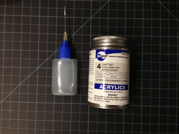
First, you need to collect your materials. For my project I used the following:
Liquid acrylic glue – I use this one http://www.interstateplastics.com/Scigrip-Weld-on…
Clear waterproof silicone caulk
2 part Epoxy glue
Large Acrylic tube – I used 10in diameter, with 1/8 in thickness
Small acrylic tube – I used tube with a 5mm inner diameter
Acrylic rod – I used 5mm
Acrylic sheet – 1/8 in thickness
Scrap wood pieces
Stepper motor – https://www.sparkfun.com/products/9238
Stepper driver – https://www.sparkfun.com/products/10267
Shaft collar with mounting screw or a universal mounting hub like this https://www.sparkfun.com/products/10267
Ardunio Uno
Solderable breadboard
12 v battery pack Batteries
Adhesive backed vinyl
Dye – I used iDye for Natural Fabrics, food coloring would work too
Rubbing Alcohol
Tools:
Power drill
Plastics drill bits
A laser cutter
Table saw
Plastics blade for table saw
Miter saw box and saw
Sandpaper
Protective glasses
Rubber Gloves
Soldering iron
Step 2: Cut All Pieces
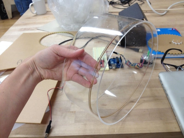
You will be cutting out the following pieces:
1 piece large acrylic tube
3 different acrylic sheets to make front and back face and middle divider
3 pieces of acrylic to use as ribbing
1 large gear
1 small gear
1 small acrylic rod
2 small pieces of acrylic tube
1 piece blue foam
-Cut the acrylic tube on a table saw. Cut it to 4.5″. Make sure you use a plastics blade. Because the tube is 10″ in diameter you need to make several passes through the table saw.
-Laser cut the 3 acrylic sheets and acrylic ribbing. These are all 1/8″. There are two chambers for the water in the tide clock, so you need a front face, inner divider and a back. The front face is a simple circle. It should meet meet flush with the outer diameter. The laser cutter cuts from the center of the line, so pieces wind up being cut a tiny bit smaller than the Illustrator file indicates. I learned this the hard way. I’ve attached my Illustrator files. The middle piece has a slit towards the bottom for the water to flow between chambers. The back face has a hole at the top where the motor attaches to the gears. Cut this hole at the top so that it is always above water level. The middle and back pieces have a center mark etched in them so that you can easily locate the center.
-Laser cut the gears. I’ve attached the Illustrator files that I used. You can adjust them for the size of your project.
-Hand saw one piece of 1/4″ acrylic rod using a saw and mitre box. Small pieces of acrylic can snap easily so I like to saw them by hand. The length of this is the depth that you want your back chamber of water to be. Mine was 1 5/8″. Saw two pieces of acrylic rod that has an inner diameter of 1/4″. These should both be 1/4″. Acrylic rod is never completely uniform so make sure that you test that your pieces fit together. These will be glued to the inner faces to hold the center rod for the gears in place.
-Cut a piece of blue foam. This will be the volume that causes the water displacement. There are several ways to cut blue foam. I used a hot wire cutter. The thickness should be about 3/4 of the depth of your back chamber. You can look at the photos to see the approximate shape of my volume.
Step 3: Assemble Body of the Clock
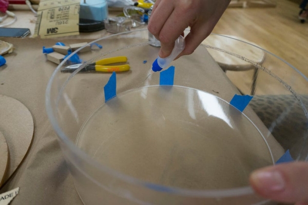
Now you need to attach all of the pieces of the body of the clock. You will use liquid acrylic glue and clear silicone caulk. Always wear protective glasses and gloves when working with acrylic glue.
-Attach the front face to the main tube. First sand the edges of the tube. The table saw can leave ridges on the edge and you want them as flat as possible. Tape the two pieces together to hold in place. Run liquid acrylic glue along all seams. Wait a few minutes for it to try.
-Attach first rib. The ribs were laser cut to be larger than necessary so that you get a tight fit. Measure them so that they are completely flush to the inside of the tube. Hand saw them to the right length. Use scrap pieces of wood or something else to brace the rib at 1/2″ from the front face. Glue in place.
-Set inner divider so that it rests on the first rib. Glue in place. The ribs insure a tighter water seal and give the center piece a structure to hold it in place.
-Run silicone caulk along the seam of the ribbing and center divider.
-Glue the 1/4″ tubes exactly in the center of both the center divider and the back face.
-Attach the blue foam to the larger gear. I did this by simply screwing them together. I’m sure there is a better way to do this but it was sufficient for my prototype.
-Set the acrylic rod into the piece of center tube on the face of the divider. Put the back face in place. Mark an even distance from the back lip so that you can insure that the back face is going in at an even level. Glue the back face in place.
-Glue the third rib to the back of the back face to hold it in place.
-Run silicone caulk along the seam of the ribbing and back face.
-Drill a small hole in the top of the front chamber. You need this as an air hold so that the water will flow between the chambers. Tape off the hole until the clock is fully assembled.
-Drill a 1/4 hold at the top of the very back of the clock body. This is how you will hang the clock on a hook on the wall.
You have assembled the body of the clock!
Step 4: Dye Water and Fill Clock
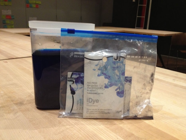
-Dye the water for your clock. I used iDye. It is very powerful, so use it sparingly. Wear rubber gloves and watch out for your clothes. Once you get the color you want, add some rubbing alcohol. This will help prevent bacteria from growing in your clock.
-Test the body of the clock for leaks. Fill it with regular water. Fill in any gaps with silicone.
-Fill the clock with the dyed water. Test the water level so that it can completely fill and drain in the front chamber.
Step 5: Assemble Electronics
Now we can move onto the electronics.
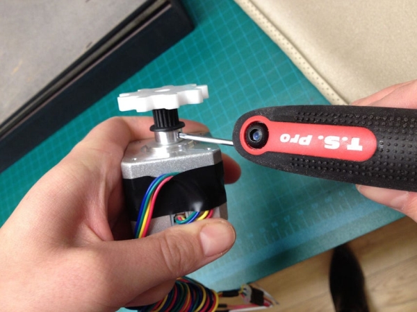
-To attach your small gear to the stepper motor you need a shaft collar. I used one with a plastic head so that I could attach it directly to the acrylic gear. To do this I used a two part epoxy glue and glued the gear to the face of the collar. Attach the collar to the stepper motor just by tightening the screw on the side of the collar.
-For this prototype I used a Easy Driver to control the stepper motor. I did this because I plan on adding programming and more complicated code to this project in the future.
-I’ve attached a diagram of the wiring setup for the stepper motor and driver. Here are two great links for setting up stepper motors:
http://www.schmalzhaus.com/EasyDriver/Examples/Eas…
http://bildr.org/2011/06/easydriver/
For this you will need an Ardunio Uno, the Easy Driver, a solderable breadboard and a 12v battery back. Solder the pieces together according to the diagram. See attached photos.
Read more: Tidal Clock
