Summary of Thermal Camera: Arduino UNO + MLX90614 IR Thermometer
Summary: This article explains wiring and software steps to build a simple thermal sensing project using an MLX90614 IR thermometer with an Arduino UNO and an RGB LED. It covers I2C connections with pull-ups, correct pin assignments for a common-cathode RGB LED, and installing the MLX90614 Arduino library and I2Cmaster before loading the provided sketch.
Parts used in the Thermal Camera: Arduino UNO + MLX90614 IR Thermometer:
- Arduino UNO
- MLX90614 IR thermometer sensor
- RGB LED (common-cathode as implied by wiring)
- 4.7K ohm resistors (two for I2C pull-ups)
- Wires/jumper cables
- 3.3V supply from Arduino
- Ground connection
- Arduino IDE and MLX90614 IR Thermometer Library
- I2Cmaster library
I did the following steps:
1) Hardware: Connect the MLX90614 (refer to the datasheet) as follows: Pin 1 on MLX (SCL) connect to ANALOG pin 5 on Arduino Pin 2 on MLX (SDA) connect to ANALOG pin 4 on Arduino Pin 3 on MLX (VDD) connect to 3.3V on Arduino Pin 4 on MLX (VSS) connect to GROUND on Arduino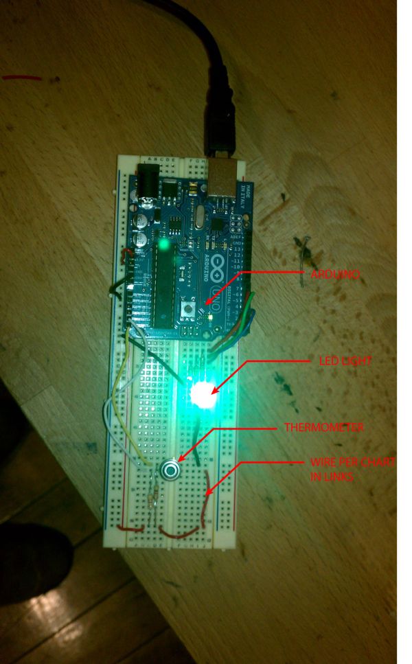 Now use “pull ups” on the SCL and SDA lines by connecting a 4.7K ohm resistor from the Pin 3 VDD line to the SCC line and a 4.7K ohm resistor from the Pin 3 VDD line to the SDA line.
2) Connect the RBG LED. Simple wiring diagram for RGB LED: http://wiring.org.co/learning/basics/rgbled.html. For the attached Arduino sketch, hook up is as follows:
Leg 1 = RED pin of the LED to PWM pin 6 Leg 2 = Ground Leg 3 = GREEN pin of the LED to PWM pin 5 Leg 4 = BLUE pin of the LED to PWM pin 3 {***NOT pin 4 as shown in the diagram above!!!!!!!!!}
3) Software: Download MLX90614 IR Thermometer Library here: http://bildr.org/2011/02/mlx90614-arduino/
To make this code work, before you load the code, or even open the Arduino program, we need to place the “I2Cmaster” in your Arduino Library.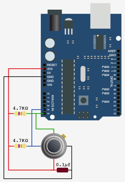 On your Mac:: In (home directory)/Documents/Arduino/libraries On your PC:: My Documents -> Arduino -> libraries On your Linux box:: (home directory)/sketchbook/libraries
Final Arduino sketch attached.
For more detail: Thermal Camera: Arduino UNO + MLX90614 IR Thermometer
- How do I connect the MLX90614 to the Arduino?
Connect MLX pin 1 (SCL) to Arduino analog pin 5, pin 2 (SDA) to analog pin 4, pin 3 (VDD) to 3.3V, and pin 4 (VSS) to GND. - Do I need pull-up resistors on the SCL and SDA lines?
Yes, use two 4.7K ohm resistors from the MLX VDD line to SCL and to SDA as pull-ups. - How should the RGB LED be wired for the provided sketch?
Wire RED to PWM pin 6, GREEN to PWM pin 5, BLUE to PWM pin 3, and the LED ground to Arduino ground. - Which Arduino pins are used for I2C with the MLX90614 in this guide?
Analog pin 5 is used for SCL and analog pin 4 is used for SDA. - What voltage should the MLX90614 VDD be connected to?
Connect MLX90614 VDD to the Arduino 3.3V pin. - Where do I place the I2Cmaster library on my computer?
Place I2Cmaster in the Arduino libraries folder: Documents/Arduino/libraries on Mac, My Documents/Arduino/libraries on PC, or sketchbook/libraries on Linux. - What library is required to run the MLX90614 sketch?
Download and install the MLX90614 IR Thermometer Library referenced in the article. - Can the wiring diagram linked in the article be used directly for pin 4 of the RGB LED?
No, the article warns not to use pin 4 for blue; use PWM pin 3 instead of pin 4 from the diagram.