The goal of this instructable is to explain how I made a wifi-connected light switch (also called remotes further). The goal of these remotes is to turn on and off several wifi-connected relays. The relays are not explained in this instructable. They are explained in a separate instructable that I made in the past: ESP8266 Wifi Switch.
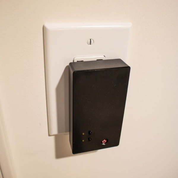
These remotes will contain up to 3 small buttons. Each button turns on/off one or more relays. An LED next to each button serves as feedback. A larger button is used for a special purpose: it turns off all of the relays. Not only the ones controlled by the remote, but all relays controlled by all remotes of the house. This is used to turn everything off when leaving to work, or going to bed.
The link between the devices is managed by Blynk. The remote microcontroller is a Huzzah Feather with ESP8266. The power to the remotes is coming from a USB wall plug (no batteries).
If you follow my instructables, you will notice that this device has a similar purpose as the one explained in a previous instructable: ESP32 Thing Wifi Remote, and you are correct. I made the following improvements from the previous model:
- The ESP32 Thing was replaced by a Huzzah Feather with ESP8266 (I had connectivity issues with the ESP32 Thing).
- The metallic buttons were replaced by plastic buttons (static electricity was sometimes transmitted to the board through the metallic buttons, requiring a reboot).
- These remotes now only control a few lights, usually the lights in one room, instead of controlling all the lights of the house with each remote (so you don’t accidentally turn on the lights in the other bedrooms for example).
- I had a battery in the older model, to be able to remove the remote from the USB plug, and still use it for a few hours. It turns out I never used this functionality, so I removed the battery to make the remote slimmer.
- I added the “turn everything off” button.
- I added the feedback LEDs.
Difficulty level: Medium
Material needed:
- 1 plastic enclosure PolyCase and PolyCase
- 1 Feather HUZZAH with ESP8266 Adafruit
- 1 half-sized solderable breadboard Adafruit
- 3 leds Adafruit
- 3 tall and narrow push buttons Adafruit
- 1 short and wide push button Adafruit
- 7 3.3k resistors Amazon
- 1 USB type-A male plug Adafruit
- wire Sparkfun
- polyurethane glue Lowes
Tools needed:
- Soldering iron Amazon
- Dremel (if you don’t have one, a utility knife would suffice) Lowes
- Drill press (if you don’t have one, a hand drill would suffice) Lowes
Step 1: Design
Microcontroller:
As microcontroller, I used the feather Huzzah with ESP8266, made by Adafruit, for the following reasons:
- It has wifi capabilities
- It is cheap ($18.95 for the assembled version)
- It is relatively small (23mm x 51mm x 8mm / 0.9″ x 2″ x 0.28″)
- It has 9 GPIOs pins (I needed 7)
The microcontroller will be powered by the 5V of a USB outlet.
4 GPIOs will be used as inputs from buttons, and 3 will be used as output to light leds. One of the buttons (the one that turns off every light) has an LED included, so it did not make sense to me to have a feedback led for this button.
Buttons:
The design for the buttons is very simple: for the 3 small buttons, I picked tactile switches, also called SPST switches. I picked the tall ones, so that they will stand out of the enclosure. For the bigger button, I also picked an SPST switch, but a shorter one, so that it will be recessed in the enclosure, the goal being that it won’t be pushed by accident. It also has an led inside, and has an I/O symbol.
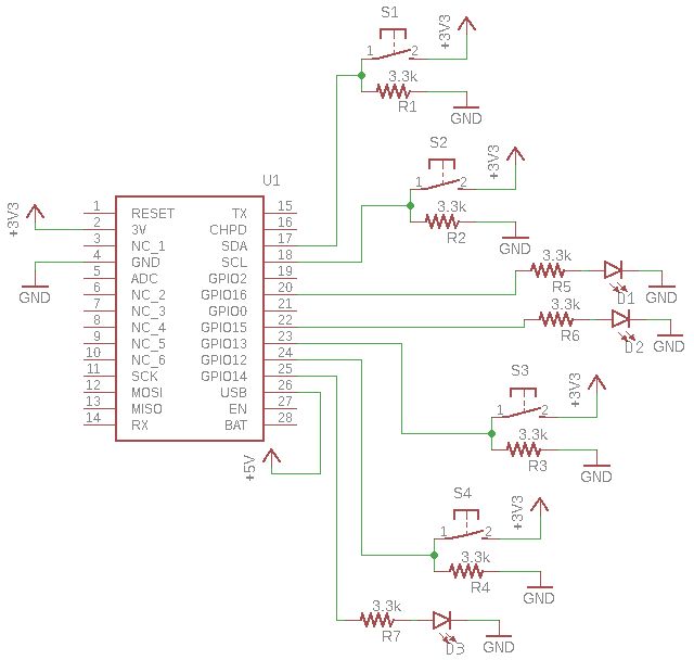
As shown in the diagram above, the switches supply ground to the GPIO through a 3.3k pull-down resistor, and supply 3.3V to the GPIO when pressed.
LEDs:
I used 5mm yellow LEDs. They are simply connected to a GPIO on one end, and to ground through a 3.3k resistor on the other end.
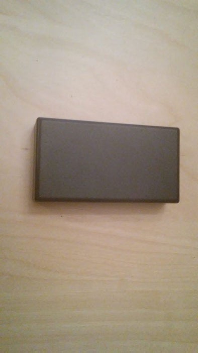
Enclosure:
For the enclosure, I needed a plastic box with internal dimensions of at least 51mm x 97mm x 11mm / 2.0″ x 3.8″ x 0.4″ . The box I picked has internal dimensions of 52mm x 100mm x 19mm / 2.0″ x 3.9″ x 0.7″ . This means that I will have to stack a few cardboard or paper behind the breadboard, to make sure that the system is pushed flush with the enclosure lid, and the buttons will stick out of the lid.
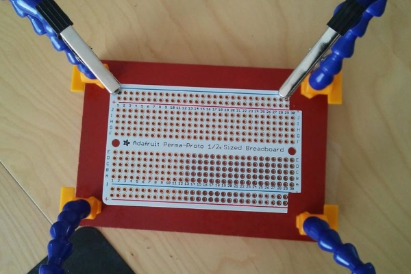
All components are soldered on a solderable breadboard. This makes it more permanent and secured than a conventional breadboard, and does not require to design a custom-made PCB. I found that the half-sized permaboard from Adafruit worked perfectly.
Step 2: Making the Board
Soldering the board is the fun part! Simply follow the wiring diagram, and everything should work according to plan. Pay special attention to the following points:
- Pay attention to the LED polarity (short lead-cathode-ground / long lead-anode-positive voltage).
- The LEDs should be as low as possible to the breadboard. Otherwise, the top of the led will be too high and stick out of the enclosure too much.
- Before soldering the Feather Huzzah, I removed the battery connector from it. We will not need it, and it is very tall, so it would not allow us to place the enclosure lid properly.
- I placed a 90-degree male – female pin connector on the “batt” pin of the Feather Huzzah, and on the ground rail. These will then be connected to the 5V and ground of the USB.
Use a third hand, or make one yourself with a piece of wood, 4 Loc-line hoses, and 4 alligator clips
Step 3: Making the Enclosure
USB plug:
Use the dremel or utility knife to make cut an opening for the USB plug in one of the upper corner of the enclosure on the rear side. Place the USB plug through it.
Make sure the USB plug is protruding 11.5 mm / 0.45″ from the back of the enclosure, and glue the USB plug in the enclosure using polyurethane glue.
Solder a wire from the +5V of the USB plug, and a wire from the ground of the USB plug. When you place your board in the enclosure, these wires will be connected to the “batt” and ground of the 90-degree male – female pin connector, respectively.
Buttons and LEDs openings:
Drill holes in the enclosure lid where the buttons and LEDs will protrude. A drill bit of diameter 4mm / 5/32″ is perfect for the small button, and 8mm / 5/16″ is perfect for the larger one. Use a countersink drill bit to make a tapered hole so it looks nice. For the LEDs, I drilled a much smaller diameter than the LED itself (1mm / 1/32″). Otherwise, I found that the LEDs I chose produce too much light. If the light switch is in a bedroom, it can be disturbing to have too much light coming from the switch.
Place an empty solderable breadboard on the enclosure lid and use a thin-tipped pen to draw on the enclosure where the holes should be drilled.
Step 4: Programming
I used the Arduino IDE for the programming of my Feather Huzzah. If you have not done it yet, download and install Arduio IDE.
To be able to use Blynk, I had to use the Blynk library for Arduino IDE. The Blynk library can be downloaded here. Follow these steps to install the library (quoted from the Blynk website):
- Download the latest release .zip file.
- Copy all these libraries to your_sketchbook_folder of Arduino IDE. To find the location of your_sketchbook_folder, go to top menu in Arduino IDE: File -> Preferences (if you are using Mac OS – go to Arduino → Preferences)
- Unzip it. You will notice that archive contains several folders and several libraries.
The structure of your your_sketchbook_folder should now look like this, along with your other sketches (if you have them):
your_sketchbook_folder/libraries/Blynk
your_sketchbook_folder/libraries/BlynkESP8266_Lib
…
your_sketchbook_folder/tools/BlynkUpdater
your_sketchbook_folder/tools/BlynkUsbScript
…
Note that libraries should go to libraries and tools to tools. If you don’t have tools folder you can create it by yourself.
The code can be found in the following Github repository: https://github.com/vjuvet/Feather-Huzzah-wifi-remote
It should be fairly well documented, but don’t hesitate to post a comment if you have any question.
In summary, this is how the code works:
A timer runs the function checkInputs every 200 ms. This function checks if a button has been pressed or released.
checkInputs:
If the button is released, it does not do anything.
If the button is pressed, it toggles the state of the switch (switchState), and calls function sendState.
sendState:
If one of the small buttons is pressed, function sendState will send the new state of the switch to the appropriate relays, through the built-in function bridge.virtualWrite.
If the bigger button is pressed, function sendState will send an “off” state to all relays through the built-in function bridge.virtualWrite.
The rest of the code is the setup, creating variables, connecting to a known wifi, etc…
Source: The Ultimate Light Switch