Summary of The Pendulum Clock
This article describes the Pendulum Clock, an art installation inspired by optical illusions seen on Seattle's Link Light Rail and University Street station. The device uses 64 LEDs to display an analog clock face or other 2D images based on pendulum motion. It requires manual pushing to operate and is controlled by an Arduino Uno with a real-time clock module.
Parts used in the Pendulum Clock:
- Arduino Uno
- DS1307 RTC
- MAX7219 LED controller
- Rotary encoder
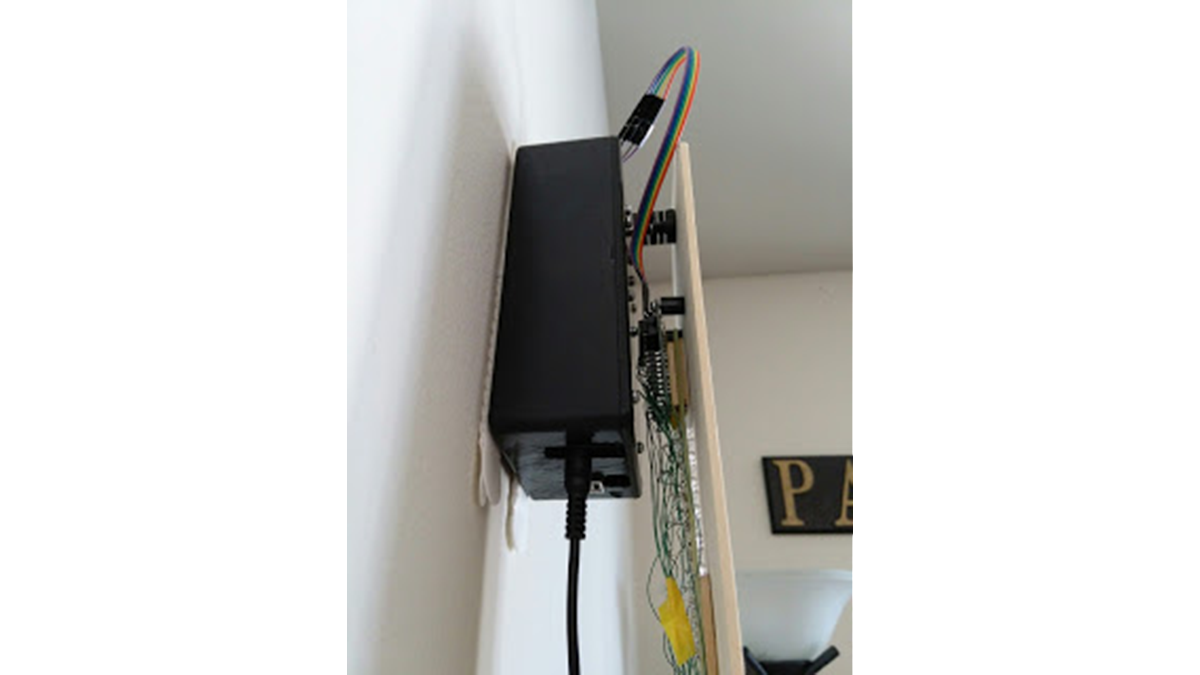
- Hammond box
- 4"x24" piece of basswood
If you’ve ever rode the Link Light Rail in Seattle to the airport, you may have glanced out of the window while traveling through a tunnel and seen playing cards illuminated on the walls. These images are not made from two dimensional screens. Each display is just a row of lights that changes rapidly as the train drives by, giving the illusion of a two-dimensional picture.
You might not see it at first, but it is showing an analog clock face that reads 2:40. Usually it takes a couple swings to see the picture. Once you see it, it becomes very easy to read the time.
The Pendulum Clock has a row of 64 white LEDs that change based on the position of the pendulum. I’ve used it to display an analog clock face, but it can be used to display any 2D image. The motion of the clock is not powered; you have to manually push the pendulum to one side to start it moving.
It’s powered by a simple Arduino Uno, a DS1307 RTC for keeping time, a MAX7219 LED controller, and a bad ass rotary encoder. The case is a Hammond box, which fit all of the components with just the right amount of room. The face is a 4″x24″ piece of basswood.
- How does the Pendulum Clock create 2D images?
The display uses a row of lights that changes rapidly as the train drives by or the pendulum swings, creating an illusion of a two-dimensional picture. - Can the Pendulum Clock display anything other than a clock face?
Yes, it can be used to display any 2D image besides the analog clock face showing 2:40. - What powers the motion of the clock?
The motion of the clock is not powered; you must manually push the pendulum to one side to start it moving. - Which microcontroller is used in this project?
A simple Arduino Uno is used to control the device. - How is time kept accurate in the project?
A DS1307 RTC is used for keeping time. - What component controls the LED lights?
A MAX7219 LED controller manages the lights. - What material is used for the face of the clock?
The face is made from a 4x24 inch piece of basswood. - Where are all the components housed?
All components fit inside a Hammond box with just the right amount of room.