The project conducted as part of the Computational Design and Digital Fabrication seminar in the ITECH masters program and was brought to you by Vanessa Costalonga, James Hayward and Christo van der Hoven.
Have you ever doubted the choices that you make?
Have you ever looked elsewhere for wisdom and clarity only to find disappointment and vagueries?
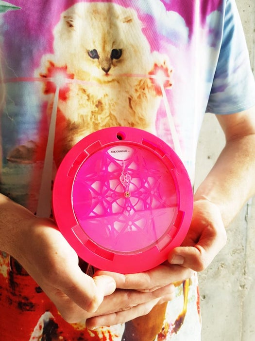
Look no further: I would like to introduce you to the moral compass.
The moral compass is a chakra aligning, energy purifying and physiologically clarifying device. Grounding itself as a talisman with the aesthetics and vocabulary choice of the late 2010’s vaporwave movement. A movement which articulated a new era of glitch art with a strong historical appropriation of the ’90s and ’80s. Our talisman is situated alongside talismans of the modern era such as the 1950’s Magic 8-ball.
Using numerology, the study of a mythical connection to numbers and meaning we have been able to bring the pseudo back to science and to center our compass answers around an eight-pointed star, commonly associated with wisdom and knowledge.
In a nutshell, the way that it works is that you ask a deep a meaningful question, and the compass will give you a deep meaningful answer, open to interpretation…
Step 1: About the Project

In this project, we will be building a device that responds to touch (capacitive sensor) and sound (microphone) to generate a movement (stepper motor) and resulting answer. It will involve building the body of the device, connecting and mounting the hardware and electronics inside, and then uploading the code to run the device. This is a project for makers with some experience working with Arduino and some experience with machines in a workshop.
If you have not worked with these parts before, we suggest you familiarise yourself with some of the concepts through tutorials or videos. Here are some examples for capacitive sensing, the microphone and the stepper motor.
Difficulty level: Medium
Step 2: Get the Gear
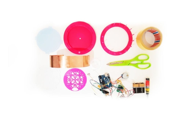
What do you need?
Electronics:
- Arduino Uno
- Stepper motor (28-byj-48) and driver board (uln2003)
- Sound Sensor (LM 393 Microphone)
- RGB Led’s
- 9v Batteries
- 6 x 220-ohm Resistors
- 1x 1 megaohm Resistor
- Prototyping gear (wires, breadboards, Led’s etc)
Materials:
- 2mm thick sheet material – 900mm x 300mm (we used plexiglass)
- Copper sheet (0.3mm thick – 430mm x 40mm ) or copper adhesive tape (430mm x 40mm)
- Spray Paint (optional)
- Glue (depends on the material)
Equipment:
- Access to a laser cutter or band saw
- Access to a soldering iron
- Access to a printer
- Access to a computer with the correct software
- Basic tools (Craft knife, steel ruler, masking tape, screwdrivers etc. )
Step 3: Assemble the Electronics
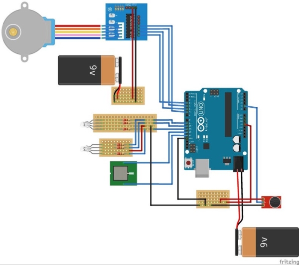
A good place to start is the assembly of the electronics.
Follow the circuit diagram and/or schematic that accompanies this step. Basically, there are three aspects to the electronics; the capacitive sensor, the stepper-motor and the microphone.
If you are confident, you can jump straight to soldering it onto some prototyping board. Alternatively, use a small breadboard that can then be placed inside the compass body.
We decided to solder the circuits onto a series of cut down proto-boards to that we can arrange the parts within the body of the compass.
One part that will require calibration is the microphone. This involves adjusting the built-in potentiometer with a small screwdriver. It is not a difficult process but can get a little frustrating. If you get stuck with this part, there are a number of tutorials that can help. Definitely calibrate the microphone before installing it on the body.
Step 4: The Code

The Arduino code for the project is not particularly complex. Essentially it comes down to three conditions:
a. It the device being held? (Or, in other words, has the capacitive sensor been enabled?)
b. Is the microphone picking up a question? (Or, is the mic reading sound?)
c. Is the question finished? (Or, has there been sound for a specified duration?)
Once all three these conditions are met the code prompts the motor to activate. This is then how the device provides an answer to the question. By this point, you have probably noticed that the device does not actually understand the question that is being asked. Instead, we are simply concerned with the duration of a sound.
For the makers that are interested in tweaking the parameters of the device have a closer look in the code. We have tried to keep the code tidy and well annotated. A nice place to start customising would be with the microphone listening durations (these have been labelled as time parameters in the code and the variables are called waitTime and cancelTime).
Once you have downloaded the code and loaded it on the Arduino, it is a good idea to test the hardware and software together. If the Led’s are not flashing and the motor not turning, you may have to do some debugging. In addition to calibrating the microphone (as mentioned in the previous step), you may also have to adjust the threshold for the capacitive sensing and the threshold for the sound sensing in the code. A good way to do that is to display what these two sensors are reading by printing them and tracking the figures in the serial monitor. More specific calibrations can then be made.
Also, don’t forget to load the libraries for the Stepper Motor and Capacitive Sensor.
<p>//== Libraries<br>#include
#include </p><p>//== RGB LED
int red_light_pin = 11;
int green_light_pin = 10;
int blue_light_pin = 9;</p><p>//== Capacitive Sensor
// pin 13 sends electrical energy
// pin 12 senses a change
CapacitiveSensor capSensor = CapacitiveSensor(13, 12);</p><p>//== Stepper Motor
#define STEPS 2038                    // the number of steps in one revolution of the motor (28BYJ-48)
Stepper stepper(STEPS, 3, 5, 4, 6);</p><p>// Constants
int microphonePin = A1;               // microphone pin on the Arduino</p><p>// Time Parameters
const long waitTime = 4500.0;         // how long after trigger to wait before motor is activated
const long cancelTime = 2000.0;       // during wait, how long of a lull will cancel wait</p><p>// Variables
int pickedUp = 400;                   // threshold for turning the compass on, when picked up
int threshold = 800;                  // sound threshold,
int randOrientation;                  // variable for a random number
int randDirection;                    // variable for a random number
int orientation;                      // variable for the speed
int volume = 0;                       // variable to hold the reading from the microphone
boolean waiting = 0;                  // boolean variable for waiting loop
boolean ledBool = 0;                  // boolean variable for LED Activation
long waitStart;                       // when trigger initiated waiting
long waitDuration;                    // how long we have been waiting
long playStart;                       // when play was initiated
long playDuration;                    // how long we've been playing
long cancelStart;                     // when the last trigger was
long cancelDuration;                  // how long of a lull we've had</p><p>//== SETUP</p><p>void setup() {
  Serial.begin(9600);
  pinMode(red_light_pin, OUTPUT);
  pinMode(green_light_pin, OUTPUT);
  pinMode(blue_light_pin, OUTPUT);
  pinMode(microphonePin, INPUT); </p><p>  randomSeed(analogRead(0));          // random seed for Stepper Motor - determines the orientation of the pointer
}</p><p>//=== MAIN BODY</p><p>void loop() {
  long sensorValue = capSensor.capacitiveSensor(30);     // store the value reported by the sensor in a variable
  //Serial.println(sensorValue);                         // enable this line of code to calibrate the capacitive sensor
  if (sensorValue > pickedUp){                           // if the value is greater than the threshold (device is picked up)
    volume = analogRead(microphonePin);                  // listening for questions
    //Serial.println (volume);                           // enable this line of code to calibrate the sound sensor
    if (!ledBool) {                                      // this statement activates the LED that signifies that compass is "listening"
      RGB_color(0, 255, 225);                            // cyan - signals Listening
      ledBool = 1;
      }
    if (volume > threshold) {                            // when the sensor detects a signal above the threshold value, waiting LED flashes
      cancelStart = millis();
      if (!waiting) {
        waiting = 1;
        RGB_color(255, 0, 255);                          // magenta - signals waiting
        waitStart = millis();
        }
      }
    if (waiting) {
      cancelDuration = millis() - cancelStart;
      waitDuration = millis() - waitStart;
      if (cancelDuration > cancelTime) {
        waiting = 0;
        RGB_color(0, 255, 255);                          // cyan - Signals listening
        }
      else if (waitDuration > waitTime) {
        waiting = 0;
        randDirection = random(1,3);                     // a random number between 1 and 2
        randOrientation = random(1,9);                   // a random number between 1 and 2
        orientation = randOrientation * 255;             // orients the needle and compass face in 1/8 incements of the stepper motor
        RGB_color(255, 0, 0);                            // red - signals answering
        if (randDirection == 1) {
          stepper.setSpeed(10);
          stepper.step(orientation);
          delay(2000);                                   // period of time the needle stays on the answer
          stepper.setSpeed(5);
          stepper.step(-1 * orientation);                // stepper motor 'homing'
          }
        else {
          stepper.setSpeed(10);
          stepper.step(-1 * orientation);
          delay(2000);                                   // period of time the needle stays on the answer
          stepper.setSpeed(5);
          stepper.step(orientation);                     // stepper motor 'homing'
          }
        RGB_color(0, 255, 225);                          // cyan - Signals listening
        }
      }
    }
  else {                                                 // this switches the led's off
    RGB_color(0, 0, 0);                                  // off - signal the compass is not being held
    ledBool = 0;
  }
} </p><p>void RGB_color(int red_light_value, int green_light_value, int blue_light_value)
 {
  analogWrite(red_light_pin, red_light_value);
  analogWrite(green_light_pin, green_light_value);
  analogWrite(blue_light_pin, blue_light_value);
}</p>
Source: The Moral Compass