Summary of The ‘Do More’ Timer, Inspired by Casey Neistat
This article details a DIY Arduino-driven countdown timer inspired by Casey Neistat's "Do More" philosophy. The project allows users to track time remaining for any event, such as the start of summer or the end of a day. It features a modular design with header pins for easy component removal and supports both USB and external power sources. Users can customize the displayed message and time parameters via code before uploading it to the board.
Parts used in the Do More Timer:
- Arduino Nano
- 16X2 LCD screen
- 15k Ohm resistor
- 1k Ohm resistor
- Male and Female Header Pins
- Wire
- General purpose PCB
- Hacksaw blade
- Solder and Soldering Iron
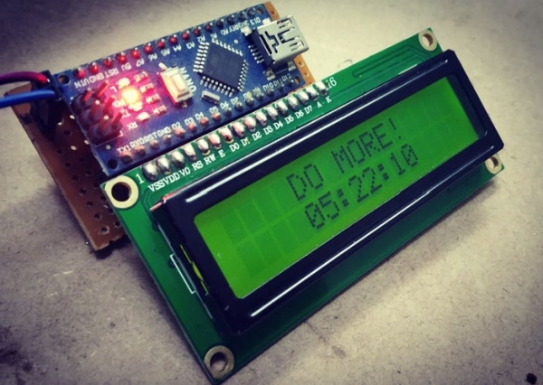
Summer, the lovely season when things happen. But sometimes we tend to forget the time. So to remind us the time left , I designed this Casey Neistat’s ‘Do More’ DIY arduino driven timer which can be programmed to display the time left from any event, the start of a day or the start of summer its on you.
All there was left to do was add a pair of Casey’s signature glasses. But I will leave that to you guys ;D
So lets get started and DO MORE!!!
Step 1: All That You Will Ever Need…
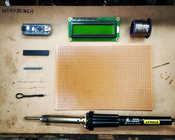
Here’s the list of things that you will need:
- An Arduino Nano (its cable and a laptop to upload the program)
- A 16X2 LCD screen for your arduino
- One 15k Ohm and One 1k Ohm resistor
- Some Male and Female Header Pins
- Bit of wire
- A general purpose pcb (and a hacksaw blade to cut it)
- Solder and a Soldering Iron
(Adult supervision is needed for this project while soldering and cutting the PCB. Please take care, even if its quite simple.)
SO after getting all this you’re gold 😀 , and lets proceed…
Step 2: The Prep
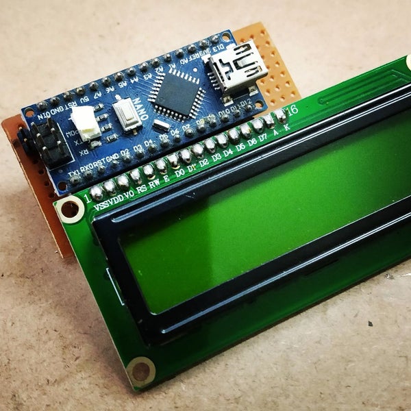
So basically I wanted this project to be flexible, i.e. you can take off the arduino and the LCD off any time you want to for other projects. To account for this modularity I designed the PCB with header pins. And also added 2 male header pins for power supply if you dont want to power it by USB.
(With this setup you can use the arduino and the LCD for displaying anything you want in the same configuration, which is an added benefit)
Step 3: Soldering the Path
I tried to minimize the amount of wiring so that the project becomes rugged and dosen’t break easily. The connections are pretty simple but you have to plan ahead how your paths should be. I have added the link for the connections.(https://www.arduino.cc/en/Tutorial/HelloWorld).
Take a marker and mark the paths on the PCB following the connections given in the link, or you can just copy what I’ve done in the image.
Now the main show :
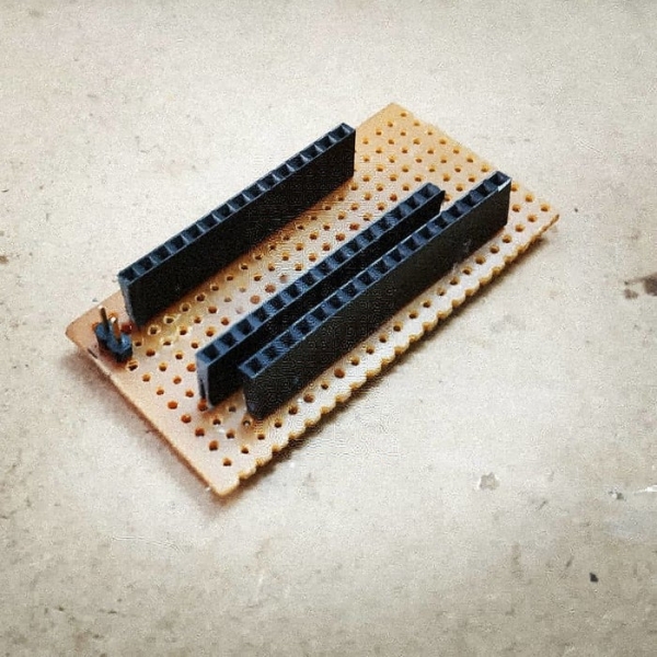
- Add the female header pins and check by trying out with the arduino and LCD, if everything fits properly.
- Solder the header pins into place (be careful 🙂 )
- Start soldering all the tracks and add the resistors later on. The above link does describe to add the potentiometer but ignore that and use the values I used. Its for setting the backlight amount, and I feel the values I chose work well.
- Carefully solder the track, it is quite troublesome to remove the solder if you commit a mistake.
- I’ve also added two male header pins to Arduino’s VIN and ground pins so that it can be powered by a external 9-12 V power supply, if you want to remove the USB cable
- Cut the excess PCB board with a hacksaw blade (Again, be careful)
- Add the arduino and the LCD
- Connect the arduino to your laptop with the USB cable and open Arduino IDE
Now time for uploading the program. I’ve added the link to it but you have to edit it a bit.
(https://docs.google.com/document/d/1tu8rqgysZhHVpN…)
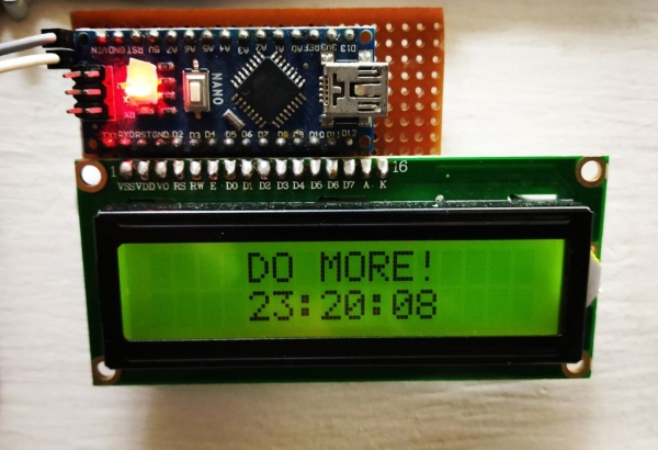
Here you can see the fields like seconds, minute , hours. Set it accordingly, I usually use it as a ‘hours left in a day’ timer so I assigned it once to the my current time (like this – H,M,S :: 23-18,59-48,0). Get creative and set it however you want to. You can also change the message by changing the text in lcd.print (“DO MORE!”);
Upload the program to the arduino.
Step 4:
Thats it fire it up and you’re good to go. Enjoy your summer and DO MORE!
Source: The ‘Do More’ Timer, Inspired by Casey Neistat
- What is the primary function of this project?
The project is an Arduino driven timer designed to display the time left from any specific event. - Can I use this timer for events other than summer?
Yes, you can program it to count down from the start of a day or any other event you choose. - How is the circuit powered if not using USB?
You can use two male header pins connected to Arduino VIN and ground to power it with an external 9-12 V supply. - Why were header pins added to the PCB?
Header pins were added to make the project flexible so the Arduino and LCD can be removed for other projects. - How do I customize the countdown duration?
You must edit the code fields for seconds, minutes, and hours to set the desired time limit. - Is adult supervision required during this project?
Yes, adult supervision is needed while soldering and cutting the PCB. - What tool is recommended for cutting the excess PCB board?
A hacksaw blade should be used to cut the excess PCB board after assembly. - How do I change the text displayed on the screen?
You can change the message by editing the text within the lcd.print command in the code.