Inspiration
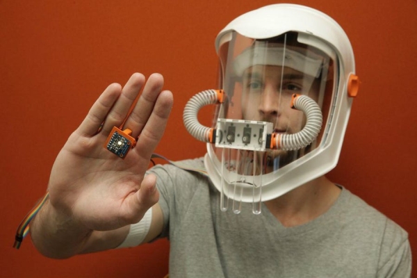
What if I told you that 2+2=Red!?!? What!?! I know this sounds crazy but for people with synesthesia this might be their reality. Synesthesia is defined as “the production of a sense impression relating to one sense or part of the body by stimulation of another sense or part of the body.” This is a complicated way of saying that people with synesthesia have blended senses. The most common type of synesthesia is called grapheme, in which numbers and letters are intuitively linked with color. So 2+2=4 but a red 4. There are a myriad of other types of synesthesia which you can read about here, but in this Instructable we are going to be designing a mask that links our sense of color with our sense of smell. Get ready to experience the world in a totally new way!
List of Necessary Materials
Full Face Mask
[2ft] Thick Elastic Band[2] NPN 2N2222 Transistors[2] 1N4001 Diodes[2] 1KOhm Resistor10,000mAh External battery
Male Pin Headers
Female Pin Headers
Ribbon Cable
Optional Materials
[5″x4″]Single Sided PCBStep 1: How Does This Work???
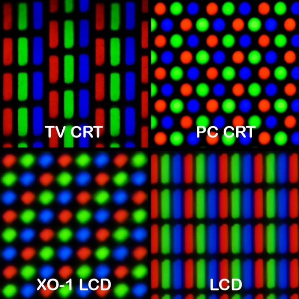
You can think of the Synesthesia Mask as a smell pixel. Analogous to the way that pixels combine varying amounts of red, green, and blue to make different colors, the mask dispenses proportional amounts of a “red”, “green”, and “blue” scent to match the color you are touching. In practice a fan from one end of the scent manifold blows air over the test tubes containing our “red”, “green”, and “blue” smells. Each servo angles its test tube cover directing air down into the test tube where it picks up the scent of the essential oil inside. The “red”, “green”, and “blue” smells mix together and are then blown by the fan on the other end of the manifold into your mask. The amount of each scent that gets blown into the mask is mapped to the red, green, and blue color value being read by the color sensor on your hand.
Step 2: Laser Cutting
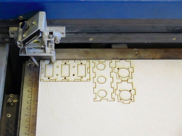
The scent manifold was cut out of 1/8″ plywood and acrylic using an Epilog laser cutter. All sides but the top and clear acrylic face of the manifold are glued together. The DXF files to laser cut these pieces are attached. If you do not have a laser cutter have no fear! Balsa wood, which can be easily cut with an X-acto knife, would make an awesome scent manifold.
Step 3: 3D Printing Parts

During this step we are going to 3D print 4 components for which the .IGS files are attached:
Test Tube Covers – These covers attach to the servos and block or allow air into the test tubes containing our scents. The greater the angle of the cover, the more air is thrust into the test tube, proportionally adding more of that scent to your mask.
Tube Connectors – Help connect the scent manifold to the mask, the outer diameter of the connectors match the inner diameter of the 3/4″ tube.
Finger Attachment – Mounts the RGB color sensor to your hand
Arm Band – This unit will house the Edison, in addition to the external battery and custom electronics. Mounting the electronics on your upper arm makes the load easer to carry and will limit the length of wire needed to run power to the mask.
Hot gluing the color sensor to an old ring would be a great alternative to the 3D printed finger attachment. Additionally, instead of 3D printing an arm band from scratch you could use a smartphone workout arm band with a solid backing to mount your electronics. Please don’t be discouraged from this project just because you see me using different tools. Hack, remix and make this project your own 🙂
Step 4: Electronics Prototyping
Break it Down!
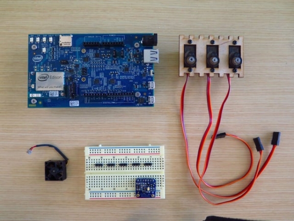
This is not a simple circuit, so lets break up all the components into subgroups and figure out how to hook them up separately. If you get lost or confused the schematics will show you exactly where every wire needs to go. If this is the first time you’ve seen schematic presented this way, check out this awesome Sparkfun tutorial on reading schematics.
Step 5: Electronics Prototyping – RGB Sensor
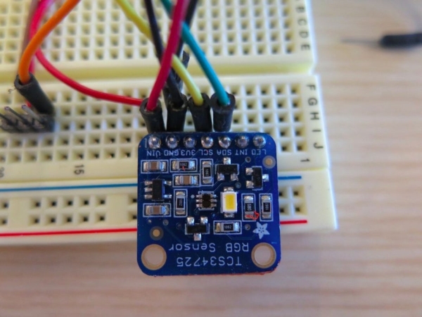
Lets start with the RGB color sensor! This sensor communicates through I2C, pronounced “I-Squared-C”, this communication protocol requires only two wires, a clock and data line and can be used to communicate to multiple devices on the same bus. First run a wires from the Edison’s 5V output and Ground to the Vin and GND pins of the RGB sensor. The clock line is labeled SCL on the sensor and gets plugged into the SCL pin on the Edison Arduino board. Do the same for the data line, labeled SDA. If this terminology sounds a bit foreign don’t worry, you can totally proceed with this guide and complete your mask, but I would highly recommend reading up a little on I2C, it’s really interesting.
Step 6: Electronics Prototyping – Servos

Next are the servos which have three wires coming out of them which are power (V+), Ground (GND) and Signal (SIG). The PWM (Pulse Width Modulation) signal that drives the servos is a generated by the Intel Edison from only a few special pins. Here we Intel provides awesome getting started and maker support forums if you need guidance along the way. I referenced the Edison hardware design files multiples times through this build.
Step 7: Electronics Prototyping – Fans

The final pieces we need to hook up are the fans. These tiny guys can draw current in excess of 100mA which could fry a pin on the Edison. We will use the handy 2N2222 transistor to amplify the very tiny current output from the Edison pin to a much larger current. If you have not worked with transistors before check out this intro article. Transistors have 3 pins which are a base, collector and emitter. Every transistor is different as to the placement of each pin, in this example I pointed out the base pin and then connected it to pin 7 of the Edison through a 1KOhm resistor.
Because we have two fans we will build another transistor circuit and hook up the base to pin 8. One final component we want to add to the circuit is a flyback diode. Place a diode around the motor with the positive end (the side with the white stripe) facing the positive line of the motor. This is to protect our Edison from any voltage spikes causes from the fan.
Step 8: Create Wiring Harness
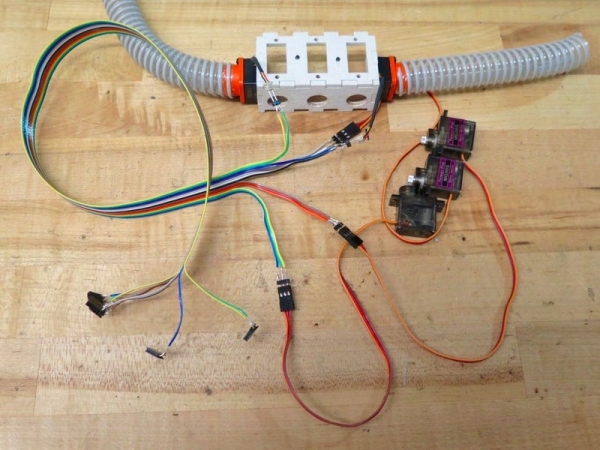
I used rainbow ribbon cable and make two wiring harness to keep all of the wires tidy. One runs from the mask down to the bicep to the arm band and the second goes down the forearm to the color sensor on your hand. I soldered both ends of the wiring harness with female pin headers, 7 for the RBG sensor, three sets of 3 pins for the servos and two sets of two for the fans.
Read more: Synesthesia Mask
