Summary of Stepper Motor Control System Based On Arduino With ULN2003 Chip
This project demonstrates a stepper motor control system using an Arduino UNO and ULN2003 driver. It features bidirectional rotation controlled by push buttons and adjustable speed via a potentiometer, with real-time status displayed on an LCD screen. The system is suitable for industrial automation, robotics, and office equipment applications requiring precise motor movement at 5V DC.
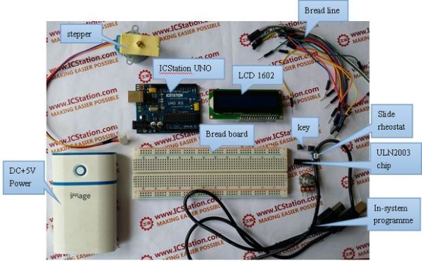
Parts used in Stepper Motor Control System Based On Arduino With ULN2003 Chip:
- Arduino UNO V3.0 R3 Board or Compatible Arduino
- 1602A HD44780 Character LCD Display Module
- 5V 4 Phase 5 Line 5VDC Stepper Motor
- 50K Ohm B50K Knurled Shaft Linear Rotary Taper Potentiometer
- ULN2003AN DIP-16 TI Darlington Transistor Array
- Trim Pot Resistor Potentiometer
- 830 Point Solderless PCB Bread Board MB-102 Test DIY
- 12X12X5mm Tact Switches 4 Legs
- Bread Board Jump Line Jumper Wire
- Dupont 20cm Color Cable Line
- +5V DC power supply
Project Summary:
This project uses ULN2003 chip to drive. The working voltage is DC5V. It is widely used on ATM machine, inkjet printer,cutting plotter, fax machine,spraying equipment, medical instruments and equipments, PC peripheral, and USB Mass Storage ,precise instrument,industrial control system,office automation,robot areas,etc.
Bill of Materials:
1.Arduino UNO V3.0 R3 Board or Compatible Arduino
2.1602A HD44780 Character LCD Display Module
3.5V 4 Phase 5 Line 5VDC Stepper Motor
4.50K Ohm B50K Knurled Shaft Linear Rotary Taper Potentiometer
5.ULN2003AN DIP-16 TI Darlington Transistor Array
6.Trim Pot Resistor Potentiometer
7.830 Point Solderless PCB Bread Board MB-102 Test DIY
8.12X12X5mm Tact Switches 4 Legs
9.Bread Board Jump Line Jumper Wire
10. Dupont 20cm Color Cable Line
11.+5V DC power supply
Firmware:
Functions
1.When start up, the stepper motor will rotate in the clockwise direction, at the same time the1602 LCD will display the stepping rate and rotating direction.
2.When you press the key1, the stepper motor will rotate in the counter-clockwise direction.
3.When you turn the potentiometer to the left or to the right, you can adjust the stepping rate of the stepper motor. At the same tine the 1602 LCD will display the current speed.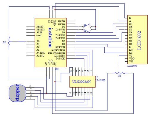
Software & Code Snippets:
#include <Stepper.h>
#include <LiquidCrystal.h>
int Iint1=0;
int Iint2=1;
int anjian1=2;
int anjian2=3;
int motorSpeed;
LiquidCrystal lcd(9,8,7,6,5,4);
const int stepsPerRevolution =200;
// 	Here set the stepper motor rotation step how much is a circle
int dim=stepsPerRevolution;
//	Set the step motor number and pin
Stepper myStepper(stepsPerRevolution, 10,11,12,13);
void setup()
{
   lcd.begin(16, 2);
   lcd.print("speed:");

   lcd.setCursor(10,0);
   lcd.print("n/min");

   lcd.setCursor(0, 1);
   lcd.print("Direction:");
   // 	Set the motor speed of 60 steps per minute

   myStepper.setSpeed(60);
pinMode(anjian1,INPUT_PULLUP);
   pinMode(anjian2,INPUT_PULLUP);
   attachInterrupt(Iint1,counterclockwise,FALLING);
   attachInterrupt(Iint2,clockwise,FALLING);
   Serial.begin(9600);
}
For more detail: Stepper Motor Control System Based On Arduino With ULN2003 Chip
- What components are required to build this stepper motor control system?
The project requires an Arduino UNO, 1602 LCD, 5V stepper motor, ULN2003 driver, potentiometers, tactile switches, breadboard, jumper wires, and a 5V power supply. - How does the system determine the rotation direction of the motor?
Pressing key1 rotates the motor counter-clockwise, while pressing key2 rotates it clockwise. - Can the stepping rate be adjusted during operation?
Yes, turning the potentiometer left or right adjusts the stepping rate, which is displayed on the LCD. - What happens when the system starts up?
Upon startup, the stepper motor rotates clockwise while the LCD displays the current stepping rate and rotating direction. - Does the project use any specific libraries for code implementation?
The firmware uses the Stepper.h and LiquidCrystal.h libraries to manage motor steps and LCD output. - What is the default speed setting configured in the setup function?
The initial motor speed is set to 60 steps per minute in the setup code. - Which pins are used for attaching interrupts to control direction?
Interrupts are attached to pin 2 for counter-clockwise and pin 3 for clockwise rotation. - Is this system compatible with USB Mass Storage devices?
Yes, the ULN2003 chip used in this project is widely applicable for PC peripherals and USB Mass Storage systems.