
Summary of How to make a Arduino LED Scroll Bar
This article guides you through building a customizable LED Scroll Bar using ten distinct LED strip segments controlled by a custom circuit board. The project involves cutting and welding LED strips, designing a PCB with an Arduino Nano and keypad using EasyEDA, and programming the system to cycle through various flash patterns via button input. It emphasizes safety regarding voltage differences between the 12V strips and 5V microcontroller.
Parts used in the LED Scroll Bar:
- LED strip
- Arduino Nano
- Dupont line
- Control board (custom PCB)
- Keypad
- Power regulator (AMS1117-5.0)
- 12 V power supply
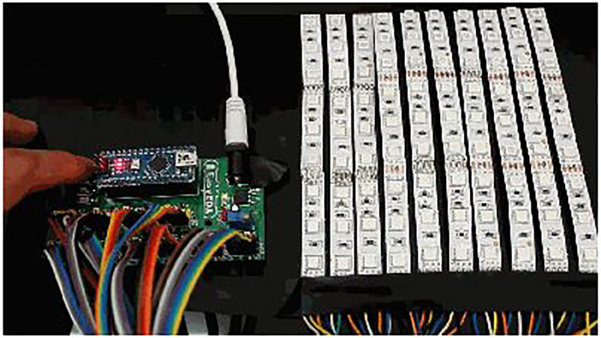
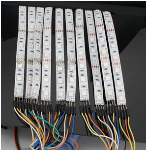
Today I want to make a LED Scroll Bar as the above picture showed. Ten LED strips can flash in different effects by using a control board.
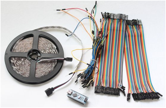
Required Components
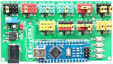
LED strip, Arduino Nano, Dupont line and a control board.
So, how to make a LED Scroll Bar?
Step 1)
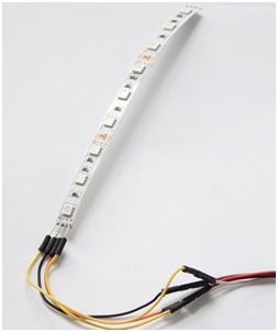
Cut the LED strip into 10 pieces and each piece has arbitrary number of LEDs.
Then, weld the traverse at an interface of the LED strip. Here I prefer to use Dupont line to connect.

Step 2) Design
Make a control board. Using the control board to control the flash pattern of LED strips. Aided by Arduino Nano and equipped with a keypad, we can make the LED strip flash in different patterns.
Step 2.1) Start with Designing Schematic
To design my circuit, I choose a free online EDA tool called EasyEDA which is a one stop design shop for your electronics projects, offers schematic capture, spice simulation, PCB design for free and also offers high quality but low price Customized PCB service. There are a large number of component libraries in its editor, so you can easily and quickly find your desired parts.
You can access the following schematic diagram through this link
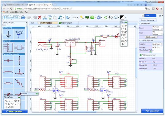
Notes: The voltage of the LED strip is 12 V and Arduino Nano is 5V. Please remember to add a power regulator such as AMS1117-5.0.
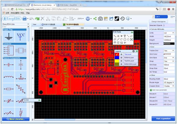
Step 2.2) Create the PCB Layout.
You can see the PCB layout in the following diagram:
Step 2.3) Make a sample
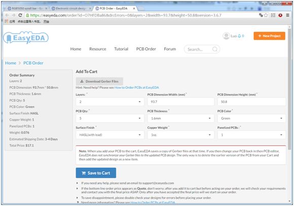
After complete the design of PCB, you can click the icon of Fabrication output above. Then you will access the page PCB order to download Gerber files of your PCB or send them to any manufacturer, it’s also a lot easier (and cheaper) to order it directly in EasyEDA.
Step 2.4) Take delivery of the PCB and receive PCB

Step 2.5) Welding
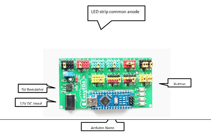
It is very easy to make a control board. Just as the following picture described, as soon as the components are welded, it is completed.
Step 3) Connection
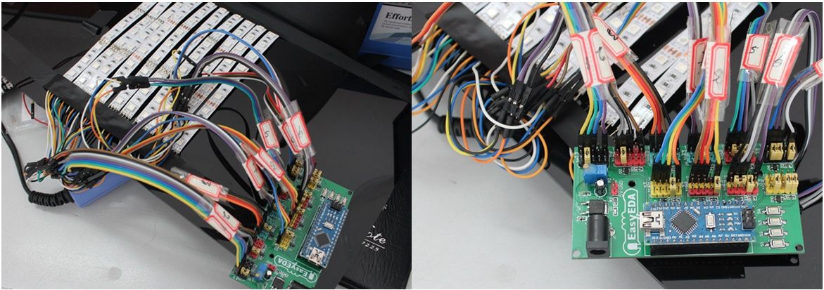
Connect the LED strip to the control board and at the same time please pay attention to the positive and negative of the terminals.
As the picture showed below.
Step 4) Download a program
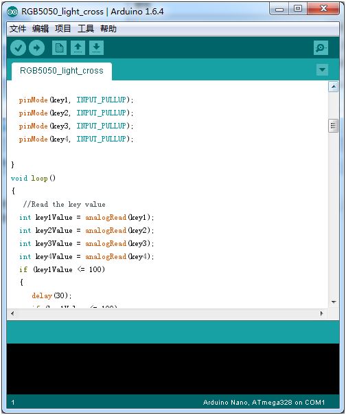
Connect it to a 12 V power supply, download a program on the Arduino Nano and run it.
Press the button to switch flash mode.
If you want, you can clone my LED Scroll Bar Schematic and PCB here.
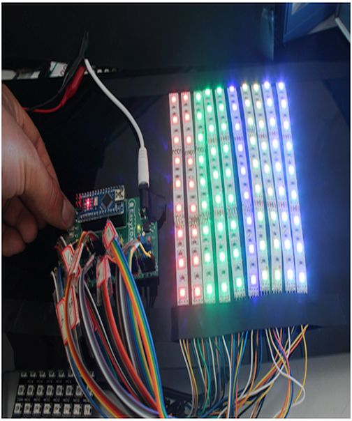
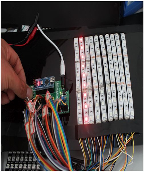
Now I completed my project of scroll bar.
Making your own LED Scroll Bar creates a lot of fun, and the results can be very rewarding. Hopefully this article will help you make a LED Scroll Bar, You can also write a program to make the LED strip flash in the way you like.
-
How many pieces should the LED strip be cut into?
The LED strip should be cut into 10 pieces, where each piece can have an arbitrary number of LEDs. -
What tool is recommended for designing the circuit schematic?
EasyEDA is recommended as a free online EDA tool for schematic capture, spice simulation, and PCB design. -
Why is a power regulator necessary in this project?
A power regulator like the AMS1117-5.0 is needed because the LED strip operates at 12 V while the Arduino Nano requires 5 V. -
How do I obtain the physical PCB after designing it?
You can download Gerber files from the fabrication output icon to order from any manufacturer or order directly through EasyEDA. -
What component allows users to switch flash modes on the device?
A keypad connected to the control board allows the user to press a button to switch flash modes. -
How are the individual LED strip segments connected to the main board?
The segments are connected to the control board using Dupont lines welded at the interface of the LED strip. -
What is required to make the LED strips flash in different patterns?
You must connect the system to a 12 V power supply and download a program onto the Arduino Nano.
