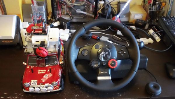
IP Control Car was launched in 2001.
I make the similar function car utilizing commercialized products.
The concept of Car No.02 is to utilize commercialized products, and I am an amateur in electrical. So, do not blame me that the system is not sophisticated, i.e. servo & speed controller control system and webcam system are not integrated, or 4 different types of batteries are used for R/C Car(7.2V), Arduino(5V), USB Device Server(12V) and Wireless Broadband Router(5V).
Step 1: Procurement
R/C Car
– Chassis Tamiya M-05Ra Chassis
– Body Tamiya 8085258 Mini Cooper Monte Carlo 94 Finished Body
– Geared Motor AO-8014 Tamiya Geared Motor 380K10 (gear ratio 10:1)
– Servo Futaba S3003
– Speed Controller Tamiya TEU-104BK
– Ni-Cd Battery 1500mAh 7.2V
Mounted devices on R/C Car
– Arduino Duemilanove
– Arduino ProtoShield Kit DEV-07914
– Bluetooth Modem BlueSMiRF
– 5V 500mA Battery eneloop mobile booster KBC-L3AS
– Webcam Microsoft LifeCam Show RLA-00007
– USB Device Server IO Data ETG-DS/US (net.USB)
– Wireless Broadband Router PLANEX MZK-MF300N
– 12V 1A Low Dropout Regulator LM2940CT-12 kit
– 5V 1A Low Dropout Regulator LM2940CT-5.0 kit
– AA battery x 20
– Battery Case (AAx10pcs) x 2
– Lubic, etc
Desktop PC side (OS is Windows XP.)
– Steering Wheel Logicool Driving Force GT LPRC-14000
– Bluetooth USB Adaptor Parani-UD100
– Wireless LAN USB Adapter GW-US300MiniS
– Wireless LAN Extender PLANEX MZK-EX300N-EZ
Software (to be downloaded and installed)
– Arduino
– Processing
– Jmyron (http://webcamxtra.sourceforge.net/)
– proCONTROLL (http://creativecomputing.cc/p5libs/procontroll/)
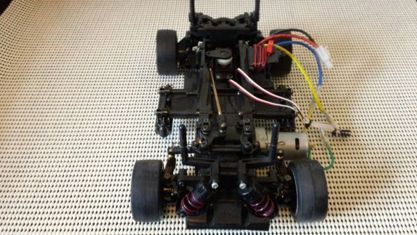
Step 2: Assembling 1
Assemble Tamiya M-05Ra Chassis in accordance with Assembly Manual. (http://www.tamiya.com/japan/download/rcmanual/m05ra.pdf)
The followings are different from the manual.
– Geared motor installation
(if you do not want a low speed car, geared motor is not necessary. Assemble with 540 motor in accordance with the manual.)
Modify A2 and B2 parts, and attach the geared motor with following parts;
Different diameter in-line collar 6mm x 4mm
Dia 4mm hollow shaft 10mm long
Dia 3mm shaft 19mm long
16T pinion gear
Adjuster 20mm long
Countersunk screw
Skip Part 11 and 12 of Assembly Manual.
– Get the center value of servo and set up speed controller
Instead of Part 19 of Assembly Manual (Checking R/C equipment), get the center value of servo and set up speed controller with connecting them to Arduino. Receiver is not required for this system.
Upload the following Arduino code to Arduino.
Arduino code
/*
* Servo & Speed Controller
* Processing —- SVSC_P
* Arduino Duemilanove —- SVSC_A
*/
#include <Servo.h>
Servo servo;
Servo speedcontroller;
int val1;
int val2;
int val3;
int servoneutral = 63;
int speedcontrollerneutral = 63;
int steval = servoneutral;
int velval = speedcontrollerneutral;
int reversea = ‘F’;
boolean reverseb = false;
void setup() {
Serial.begin(115200);
servo.attach(9);
speedcontroller.attach(10);
}
void loop() {
if(Serial.available()>2){
val1 = Serial.read();
val2 = Serial.read();
val3 = Serial.read();
Serial.print(65,BYTE);
}
if(val1>=128 && val2<128 && (val3==’F’||val3==’R’) ){
steval = val1 – 128;
velval = val2;
reversea = val3;
}else if(val1<128 && (val2==’F’||val2==’R’) && val3>=128){
steval = val3 – 128;
velval = val1;
reversea = val2;
}else if((val1==’F’||val1==’R’) && val2>=128 && val3<128){
steval = val2 – 128;
velval = val3;
reversea = val1;
}
servo.write(steval);
if(reversea==’R’ && reverseb==false){
for (int i=1; i <= 5; i++){
speedcontroller.write(speedcontrollerneutral);
delay(15);
}
reverseb = true;
speedcontroller.write(velval);
}else if(reversea==’F’){
reverseb = false;
speedcontroller.write(velval);
}else {
speedcontroller.write(velval);
}
}
Connect servo and speed controller to Arduino.
(Servo –> D9, 5V, GND Speed Controller –> D10, 5V, GND)
Run the following Processing code.
Processing code
/*
* Servo & Speed Controller
* Processing —- SVSC_P
* Arduino Duemilanove —- SVSC_A
*/
import processing.serial.*;
Serial port01;
int x;
int y;
int steval = 63;
int velval = 63;
int reversea = ‘F’;
void setup(){
size(127,127);
stroke(128);
port01 = new Serial(this,”COM18″,115200); //COM No. varies by each PC.
port01.clear();
}
void draw(){
background(51);
line(x, 0, x, height);
line(0, height-y, width, height-y);
}
void serialEvent(Serial p){
steval = 127 – x;
velval = y;
if(velval>=63){reversea=’F’;} else{reversea=’R’;}
if(p.available()>0){
port01.write(steval+128);
port01.write(velval);
port01.write(reversea);
print(steval);print(“,”);print(velval);print(“,”);println(char(reversea));
}
}
void keyPressed(){
if(key==’s’){
x = 63;
y = 63;
steval = 127 – x;
velval = y;
port01.write(steval+128);
port01.write(velval);
port01.write(reversea);
}
else if(keyCode == RIGHT){
x += 1;
if(x > 127){x = 127;}
}
else if(keyCode == LEFT){
x -= 1;
if(x < 0){x = 0;}
}
else if(keyCode == UP){
y += 1;
if(y > 127){y = 127;}
}
else if(keyCode == DOWN){
y -= 1;
if(y < 0){y = 0;}
}
}
Once the display window appears, press ‘s’ key to start serial communication.
‘Right’ and ‘left’ arrow keys relate to servo (steering) and ‘up’ and ‘down’ ones relate to speed controller (forward, backward and speed).
Make the first figure 64 in the Processing lower black screen by pressing ‘s’ key.
Attach a servo arm as much as central. After attaching the servo arm, get the center value of servo. (Press ‘right ‘and/or ‘left’ arrow keys, make the servo arm center, then read the first figure.)
Set up speed controller in accordance with the speed controller setup manual.
(Press ‘s’ key, then the second value becomes 63 as neutral. Press ‘up’ arrow key continuously, then the second value becomes 127 as forward max. Press ‘down’ arrow key continuously, then the second value becomes 0 as backward max.)
Disconnect the servo and the speed controller from Arduino.
Low dropout regulator kits (12V 1A and 5V 1A)
Resistance
LED
Switch
Terminal
Heat Sink
For more detail: Steering Wheel Drive R/C Car with Arduino