Hello everyone. I am a graphic designer with a restless soul (my site www.inoace.com). I loved doing electronics years ago and than got busy with life and job. I am now blessed with some time ( rare now a days 😛 ). This is my first microcontroller / arduino based project.
Edit: Just a tip, I was unable to make DHT11 work as it was showing same humidity all the time. Later i resolved this by using the same pin as of default in Adafruit’s DHT11 library (pin 2) and its working like charm.
Edit 2: I learned that median filter is better than running average filter because median filter takes the center reading, thus less effected by the peaks of noise than running average.
Disclaimer: Let me warn you that these are finding of real world that I found may differ from simulations or online schematics / tutorials. I may be wrong in assuming some results, but that are my findings and i intend to keep learning. All the things i did are available in shape of good tutorials on instructables or youtube, I just merged them as per my taste. My aim is to just share my experience, so do some research and you are responsible for each of your actions.
Purpose:
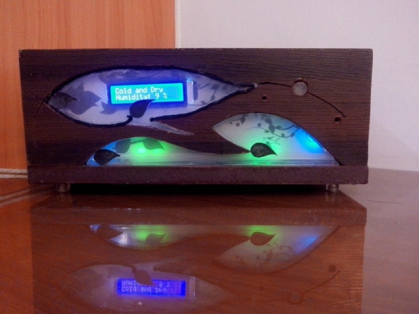
Sparrow will be assisting me in
- monitoring my PC temperature and display it on lcd (northbridge chip temperature to be exact)
- after adjustable interval, PC case fans run at adjustable speed
- if PC is hot above adjustable limit – fan runs at adjustable speed
- Room Ambient Temperature and display on LCD
- Ambient Light sensor (10W led turns on in dark)
- Dancing LEDs
Purpose of this instructable:
Learned few things from new comers perspective, so want to share it and may save other people from going through same frustration.
Step 1: Planning
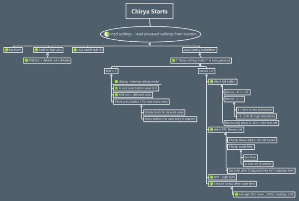
I have used Xmind (free) for mapping and managing me project and made a number of features that i wanted in my project. The attached images are snaps and also xmind files for anyone who want to use them.
The Magnifying glass 😀
Since there was a lot of soldering involved and i dont want to bend over the board too much to get a good look.
With the aim to DIY i made a magnifying glass stand with old headphone strip and spare magnifying glass that i got form scrap for only 20 rupees 😀
Scrap put to good use and saved me from back / eye strain.
Step 2: Clean Power Is Very Important
Discovery 1:
Arduino on USB might be inaccurate in situations (in my experience) if taking critical readings, try running it from external power source. I was getting very unstable readings as i was using 2 power sources during tests – Arduino from USB and all other circuits from external power supply (due to higher load).
Discovery 2:
A lot on circuits online may skip on quality of power supply. I learned the hard way , clean power is very important. In real world you wont find DC voltage = simple straight voltage, but only less wavy voltage than AC voltage.
During my project completion i discovered that my +5v supply line is having a lots of noise (due to 5 PWM ICs and PWM driven fans and power LED). I don’t have oscilloscope so i connected and small speaker with capacitor in series to 5V power lines. This made speaker play all noise that was in 5v supply (and it was a lot).
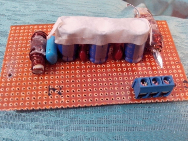
To resolve the problem with LC Filter (google it) , i used some chokes,
made them by winding spare coated copper wire on plastic pipe and adding 820uf capacitor, this made it to decrease frequencies above 69Hz . Good thing for me as my pwm was at 80hz. I made 1 each for 3 circuits boards of my project.
After using chokes for each board and think wire for ground I SUCCESSFULLY 😀 eliminated all noise (only very faint high frequency, which I suspect was from regulator) anyway noise was way lower than previous and all my sensor readings got stable).
I wrapped the board in almunium foil and grounded it to remove any EMF or noise the coils might produce (just as a precaution). Used silicon to secure the nails in coils.
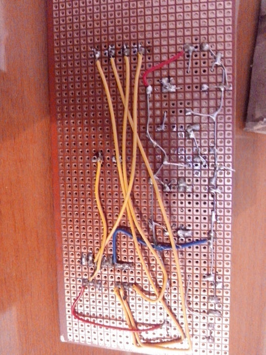
Step 3: RGB LEDs Board
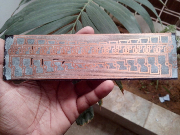
I used mix of PCB and veroboards as per ease and availability. Wiring 16 RGB leds (RBG leds in my case) would be quite messy as there would be 48 wires if done with point to point. So PCB was way to go. Used the toner transfer method (google it).
I have also attached pcb pdf (commented for ease) for leds wirring part.
All the LEDs are powered via 3 dedicated Shift register ICs 74HC595
PROBLEM FACED HERE:
Since I am new to this side, I didn’t took into consideration the max current 74HC595 can output i.e. 56ish milliamp. I used the common 220 Ohms resistors used everywhere on internet, here are the current drawn by leds:
Red leds : 12.5 ma X 16 = 200 ma ( 3 times the limit)
Green and Blue: 7.5 ma x 16 = 120ma ( 2 times the limit)
this mean that i cannot drive all leds at one, even if i decide to live on the edge and IC’s life would be very limited (if at all).
SOLUTION:
Upon realization that I am way above current limit, I had to replace the 220 Ohms with 1K ohms for Green / Blue and 1.2K for Red leds. The light were a bit less bright, but still plenty of light and everything in optimal range.
Step 4: Input and Sensors
Input board comprised of :
- an analoge multiplexer CD4051, (this is used with arduino to add more input pins).
- 2 x LM35 sensors (room temperature and PC case temperature)
- DHT11 – humidity and temperature sensor
- 2 x buttons for changing settings
- 1 x potentiometer for changing settings
Problems
Dust is a major problem in my are specially in this time of year – I covered all fan ducts with a fine cloth so now it fine dust that comes in 😀
Switches can bounce (google switch bouncing) and lm35 can pick up noise.
1- To resolve the matter I have used software and hardware solution. Hardware solutions are the green capacitors 104J for debouncing and large capacitor near LM35 supply line for filter any noise that may be in power supply line.
Quick info i found:
http://www.lh-electric.net/tutorials/gnd_loop.html… for deeper understanding read :
http://www.analog.com/library/analogDialogue/archi…
2 – Also used star grounding technique to avoid any ground loops.
3 – Used shield wire and snubber with PC sensor due to longer wire (also mentioned in LM35 data sheet – google it)
Step 5: Casing
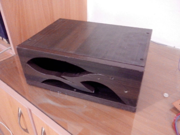
– Casing was made out of laminated Lasani wood sheet (MDF). Had a jigsaw cutter so tried to made it a fancy box to match the name of sparrow. (not yet good at wood work but definitely going to improve my skills)
– For the foots of case, I simply cut the silicon tube and screwed it to bottom.
– For front panels I used cheap plastic container and with paper cutter cut it as per openings.
Additionally:
I have also pasted aluminum sheet to the base of case and grounded it to reduce chances of wires picking up interference from atmosphere. To eliminate the chances of things shorted i paste cardboard over it so its non conductive.
Step 6: Reducing LCD Pins
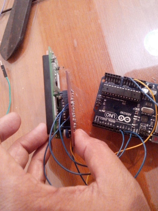
By default LCDs used 6 pins on arduino and that’s a lot for small arduino. I googled and found some good tutorials, but this worked for me, now only 3 wires instead of 6, YAAY! SAVINGS :
http://rowansimms.com/article.php/lcd-hookup-in-se…
(Above tutorial used some modified LCD library. It was hard to find library link, I had to google a bit, I am attaching the LCD Library which worked with above tutorial only for the sake for ease of new comers, All rights are reserved as per original creators. Let me know if i am breaking any copyrights, I will comply )
Not much problem here but the funny thing that i made PCB without mirroring the design, and pins are not opposite. now i had 2 options , redo the pcb or I flipped the IC legs 😛 (i.e. the printed side of ic is downside now) haha.
Step 7: Coding
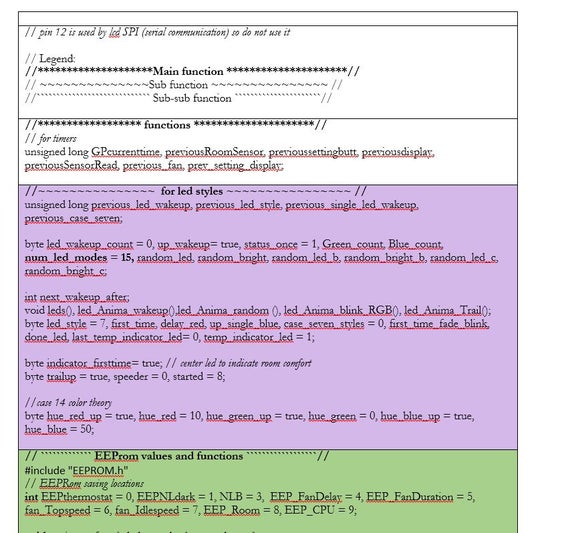
As i mentioned at start that I am designer by profession, so coding was something alien to me, but thanks to tons of tutorials examples and code out there i made my way through it and compiled 8500 words of code for the project. That was plenty of things and management in Arduino Sketch software was not enough, i returned to word made tables for each section and color coded them. This made browsing through sections easier.
I used headline with several styles to mark main function and sub functions.
For PWM functions I used Shift PWM (software pwm from http://www.elcojacobs.com/shiftpwm/ ) Thanks to him for hardwork.
For Long / Short press of buttons, I used this great tutorial.Thanks to author for effort :
https://www.instructables.com/id/Arduino-Dual-Function-Button-Long-PressShort-Press/
Step 8: Non Blocking Refreshing Delay of LCD
In arduino when we enter in a loop or void or case, it may repeat manytimes, more than you may want it to. People often used return or delay to avoid such condition if necessary.
LCD when connected to Shift register is a bit slower (not need to refresh it 75hz per second anyway :P)
so when we enter a case it may try to show same value multiple times a second and this creates a flickering effect. Since I am not monitoring realtime data i need LCD to only refresh once when it shows something. so i created a byte “refreshcount” whenever the timer thinks its time to display next item, it does two thing
+1 to item number counting
reset refresh count to 1
Now it enters the case and if refresh count is 1 it allows to read rest instructions in if statement. and immediatly makes refresh count to “0” so when when next time it loops lcd is not refreshed, this stable and non flickering reading. same repeats for every case.
reset refreshcount > display on LCD > no more refresh
here is the arduino code
case 5: // CPU Temp
if (refreshcount == 1)
{
lcd.clear();
lcd.setCursor(0, 0);
lcd.print(F(“Computer Temp”));
lcd.setCursor(0, 1);
lcd.print(CPU_temp, 1);
lcd.print(F( ” C”));
refreshcount = 0;
}
Read more: Sparrow – My Assistant