Summary of Solar Panel Battery Charge Controller Using Arduino
This article details an Arduino-based solar panel battery charge controller. It utilizes an ACS712 Hall effect sensor for current measurement and voltage dividers to monitor solar input and battery levels via a 10-bit ADC. The system controls a MOSFET switch using PWM or timing routines, indicated by LEDs for low voltage, charging status, and full charge. The code allows serial monitoring of settings and dynamic adjustment of charge cycles based on battery voltage.
Parts used in the Solar Panel Battery Charge Controller Using Arduino:
- Arduino board
- Solar panel
- Battery
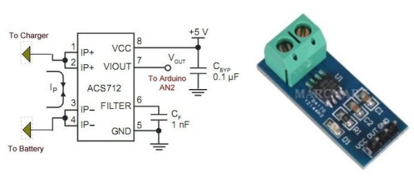
- ACS712 Hall effect sensor
- MOSFET transistor
- Voltage divider resistors (15k and 2.2k)
- LED indicators (Red and Green)
- Power box enclosure
This is an updated version of Solar Panel Charge Controller Using Arduino.
Solar Panel Battery Charge Controller Using Arduino
Pictures of Power box and Arduino solar charge regulator:
Charge Regulator with Power Box
Connections to Regulator
Inside the Box
The output voltage of the ACS712 is 2.5V with no input while the spec sheet specifies 66 to 185 mV/A output sensitivity. That’s a broad range and given the errors of Arduino’s 10-bit ADC this gives approximate current output. Good enough for most applications.
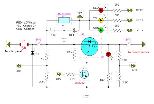
The LED1 indicator ‘bad’ meaning the input voltage below the charging voltage when on.
 DP3 turns on charge switch MOSFET transistor. Can use PWM or a simple timing routine. Will blink on/off with charge cycle. (Charge enable). The LED in the new circuit is merely an indicator.
LED2 indicator fully charged battery. (DP10)
A 10-bit analog-to-digital converter (ADC) has a step voltage of about 4.9 mV over a 5-volt range. This relates to the charge point (CP) variable.
To measure input voltage from the solar panel and the voltage on the battery we use a voltage divider to drop the voltage below 5-volts.
This uses two resistor voltage dividers (15k and 2.2k) which produces a voltage of about 1.7 – 1.9 volts when fully charged. This equates to about decimal 346 – 388 (when divided by 4.9mV) from the ADC and is compared to the charge point variable CP.
/* Solar cell battery charger/regulator

 Refer to:

 http://www.bristolwatch.com/solar_charger.htm

 DP12 LED1 indicator 'bad' meaning the input
 voltage below charging voltage.

 DP11 indicates charge on.

 DP10 LED2 indicator fully charged battery.

 DP3 turns MOSFET ON-OFF and can be
 used for PWM.

 AD0 measures Vin;

 AD1 measures Vbat;

 AD2 measure current from ACS712 Hall
 sensor for current measurement.

 This uses two resistor voltage dividers
 (15k and 2.2k) which produces a voltage
 of about 1.7 - 1.9 volts when fully charged.
 This equates to about decimal 346 - 388
 (when divided by 4.9mV) from the ADC and
 is compared to the charge point variable CP.

 Note the 4.9 mV was derived from the
 10-bit ADC which equals 1023: 5V / 1023 = 4.9mV

 Note line "chon = CP - y * 100" when
 uncommented the charge 'on' time will
 decrease gradually as battery is more
 charged. When fully charged the charge voltage
 is disabled.

 This also has the ability to monitor system
 settings through the serial port.

 */

#define Vin 0 // AD0
#define Vbat 1 // AD1

#define Ioutput 2 // AD2 read ACS712 current

#define LED1 12 // red low Vin
#define LED2 10 // green charged
#define  ChargeON 11 // charge current on
#define POWenable 3

// for use with PWM DP3
#define FULL 255
#define HALF 128
#define QUARTER 64
#define OFF 0

int x;
int y;

// these two variables can be changes
// for differing on/off times.
int chon = 5000; // charge on time
int choff = 2000; // charge off time

int CP = 310; // charge point variable
// CP sets the battery charge voltage level. Can vary from 300-340.
void setup()   {

  pinMode(LED1, OUTPUT);
  pinMode(LED2, OUTPUT);
  pinMode(ChargeON, OUTPUT);
  pinMode(POWenable, OUTPUT);

  digitalWrite(LED1, HIGH);
  digitalWrite(LED2, HIGH);
  digitalWrite(ChargeON, HIGH);
  digitalWrite(POWenable, LOW);

  Serial.begin(9600);

  delay(500);}

void loop()   {

  Serial.print("CP = ");
  Serial.println(CP);

  x = analogRead(Vin);
  // voltage from solar panel
  //under CP on ADC indicates not
  // enough voltage to charge battery
  // ~ 0.041 is derived from reading the
  // voltage with a DVM
  // the dividing by the returned
  // int value.
  Serial.print(x);
  Serial.print("   ");
  Serial.print("Vin = ");
  Serial.println(x * .041);

  y = analogRead(Vbat);
  // voltage on battery to be charged
  // over or equal to CP on ADC indicates
  // fully charged battery
  Serial.print(y);
  Serial.print("   ");
  Serial.print("Vbat = ");
  Serial.println(y * .041);

  // red LED
  if (x < CP) digitalWrite(LED1, LOW);
  else digitalWrite(LED1, HIGH);
  // LED on indicates low or no input voltage

  // green LED
  if (y > CP) digitalWrite(LED2, LOW);
  else if (y <= CP) digitalWrite(LED2, HIGH);
  // LED on means battery is charged
  if ((x > y) && (y <= CP) && (x > CP))  {
    // check input voltage and voltage on battery
    // turn on charge cycle if voltage input
    // good AND battery voltage low.

    if (y <= CP)   { // turn on voltage to battery
      // uncomment below will shorton ON time as charge
      // nears completion.
      // chon = (CP - y) * 100;

      // turn on charge LED
      digitalWrite(ChargeON, LOW);

      // charge switching transistor
      // can be pulse-width modulated
      // four values are OFF, QUARTER, HALF, FULL
      // This uses DP3.
      analogWrite(POWenable, FULL);

      // print chon value
      Serial.print("chon = ");
      Serial.print(chon);
      Serial.print("   ");

      delay(2000);

      // this section read a Hall effect current sensor
      // if attached. It read about 510 with no current flow
      // 1 amp causes a change of 40 or .2v as measured
      // with a DVM. Thus .2 / 40 = .025
      // This can be used to display charge current.
      // float temp = (analogRead(Ioutput) - 510) * .025;
      // This could tested for heavy charge current from
      // a nearly dead battery which can be limited to
      // a safe value by cutting the duty cycle back
      // POWenable to QUARTER or HALF.
      int temp = analogRead(Ioutput);
      Serial.print(temp);
      Serial.print("    I out = ");
      Serial.print((temp - 506) * .0283);
      Serial.println(" amps. ");

      delay(chon); // ON wait
      digitalWrite(ChargeON, HIGH); // Charge LED off
      analogWrite(POWenable, OFF);  // turn off MOSFET
    }

  } // end if

  // turn off charge enable
  delay(choff); // OFF wait
}
if ((x > y) && (y <= CP) && (x > CP)) {
// check input voltage and voltage on battery
// turn on charge cycle if voltage input
// good AND battery voltage low.
if (y <= CP) { // turn on voltage to battery
// uncomment below will shorton ON time as charge
// nears completion.
// chon = (CP - y) * 100;
// turn on charge LED
digitalWrite(ChargeON, LOW);
// charge switching transistor
// can be pulse-width modulated
// four values are OFF, QUARTER, HALF, FULL
// This uses DP3.
analogWrite(POWenable, FULL);
// print chon value
Serial.print("chon = ");
Serial.print(chon);
Serial.print(" ");
delay(2000);
// this section read a Hall effect current sensor
// if attached. It read about 510 with no current flow
// 1 amp causes a change of 40 or .2v as measured
// with a DVM. Thus .2 / 40 = .025
// This can be used to display charge current.
// float temp = (analogRead(Ioutput) - 510) * .025;
// This could tested for heavy charge current from
// a nearly dead battery which can be limited to
// a safe value by cutting the duty cycle back
// POWenable to QUARTER or HALF.
int temp = analogRead(Ioutput);
Serial.print(temp);
Serial.print(" I out = ");
Serial.print((temp - 506) * .0283);
Serial.println(" amps. ");
delay(chon); // ON wait
digitalWrite(ChargeON, HIGH); // Charge LED off
analogWrite(POWenable, OFF); // turn off MOSFET
}
} // end if
// turn off charge enable
delay(choff); // OFF wait
}
For more detail: Solar Panel Battery Charge Controller Using Arduino
- How does the system measure current?
The system uses an ACS712 Hall effect sensor connected to analog pin AD2 to read current flow. - What is the function of the red LED indicator?
The red LED indicates bad input voltage, meaning the solar panel voltage is below the required charging level. - Can the charge switch be controlled using PWM?
Yes, the DP3 pin can turn the MOSFET on and off using PWM or a simple timing routine. - How are voltages from the solar panel and battery measured?
Two resistor voltage dividers with 15k and 2.2k resistors drop the voltage below 5 volts for the ADC. - What happens when the battery is fully charged?
The green LED turns on, and the charge voltage is disabled when the battery voltage exceeds the charge point variable. - How is the step voltage of the ADC calculated?
The 10-bit ADC has a step voltage of about 4.9 mV derived from dividing 5 volts by 1023. - Does the code allow for serial monitoring?
Yes, the system monitors system settings through the serial port at 9600 baud. - How can heavy charge current be limited?
The duty cycle can be cut back to QUARTER or HALF values if the current from a nearly dead battery is too high.