There are many types of security systems used all over the world and Digital Code Lock is one of them. We have already covered many digital locks with simple 16×2 LCD using Arduino, Raspberry Pi, 8051 etc. Here we are going to build a Smart Phone Controlled Digital Lock using TFT LCD and Arduino Mega. This lock can be controlled wirelessly via Bluetooth, using your Android phone, within the range of normal Bluetooth that is 10 meters. User needs to enter the Predefined password from his Android Phone, if password is correct TFT LCD shows the “CORRECT PASSWORD” message and if password is wrong then LCD shows the “WRONG PASSWORD” message.
By using this Lock, you can open the door lock, while walking, even before reaching to it. This will save your time and you don’t need to carry the keys and lock can be opened easily with your Phone.
Required Components:
- Arduino MEGA
- HC05 Bluetooth Module
- USB Cable
- Connecting wires
- Buzzer
- 2.4 inch TFT LCD Shield with SPFD5408 controller
- Android Mobile phone
- Bluetooth terminal App
- Breadboard
Circuit Diagram and Explanation:
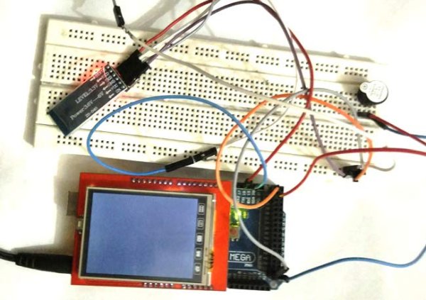
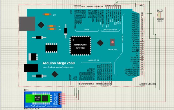
Circuit of this Smart Phone Controlled Digital Lock is simple; we only need to connect Bluetooth Module HC05 and TFT LCD Shield to the Arduino. TFT LCD shield can be easily mounted on Arduino, we just need match the alignment of pins and ensure that GND and Vcc pins of Arduino should be mounted on GND and Vcc pins of LCD. You also need to install the Library for TFT Touch Screen LCD, learn more about Interfacing TFT LCD with Arduino here.
HC05 is powered by Arduino Vcc and GND Pins, TX of HC05 is connected to RX1 of Arduino and RX of HC05 is connected to TX1 of Arduino. One pin of buzzer is connected to GND of Arduino and other to pin 22 of Arduino.
Configuring Bluetooth Terminal App for Arduino:
To operate this Digital lock through our Android Smart Phone, first we need to install an Android Mobile App named Bluetooth Terminal. Bluetooth Terminal App is compatible with Arduino. This App can be downloaded from the Google Play Store, and can be easily configured by following below Steps:
1. First download it from Google Play Store and install it in your Android mobile phone.
2. Power up your ‘Bluetooth controlled Digital Lock system circuit’.
3. Open the app and go to option ‘connect securely’.
4. You will find HC05 device to pair.
5. Give 1234 passkey to connect with your Android Phone, like we use to connect other Bluetooth Devices.
Working Description:
In this Arduino Based Security System, we have used three major components which are Bluetooth Module HC05, Arduino Mega Board and 2.4 inch TFT LCD Shield.
Here four digit Password is entered by user through Android Smart Phone using Bluetooth Terminal App and sent to the Arduino via Bluetooth. Arduino receives the data, sent by Android Phone, using Bluetooth Module HC05 and display it on SPFD5408 TFT LCD. Arduino compares the user entered Password with the Predefined password (1234), and displays the message accordingly. It displays the message “WRONG PASSWORD” if password don’t match and display the message “CORRECT PASSWORD” if password matches. A buzzer is also used for alarm indication, which beeps when password entered is wrong. Also Check the Video, shown at the end, to understand its operation.
We can also change the password to our choice by changing the Arduino Code, it has been explained in ‘Programming’ section below.
Programming Description:
To program this Bluetooth Controlled Digital Lock, we have used some libraries for displaying data on TFT LCD, which are given below. All the libraries come in one rar file and can be downloaded from given this link. Click on ‘Clone or download’ and ‘Download ZIP’ file and add to your Arduino library folder. This library is needed for proper functioning of TFT LCD.
#include <SPFD5408_Adafruit_GFX.h>    // Core graphics library
#include <SPFD5408_Adafruit_TFTLCD.h> // Hardware-specific library
#include <SPFD5408_TouchScreen.h>
Initialization of LCD input-output, and serial communication for Bluetooth module are performed in void setup() loop. Pin number 22 of Arduino is interfaced to the buzzer and the other pin of buzzer is interfaced to ground of Arduino Mega. The Bluetooth module is interfaced with Serial1 port of Arduino Mega and powered by 5V supply of Arduino Mega.
fillScreen() function is used for clearing the LCD.
void setup() {
  // put your setup code here, to run once:
  Serial.begin(9600);
  Serial1.begin(9600);
  tft.reset();
  tft.begin(0x9341);
  tft.setRotation(0);
  tft.fillScreen(WHITE);
  tft.setCursor (40, 50);
  tft.setTextSize (2);
  tft.setTextColor(BLACK);
  tft.println("E  N  T  E  R*  P  A  S  S  W  O  R  D ");
  delay(5000);
  tft.fillScreen(WHITE);
  pinMode(22,OUTPUT);
}
In void loop() function, setTextSize(4) sets the size of text and setTextColor(colorName) sets the color of text. The arr[] is the array in which we have stored the predefined four digit password and the Input[] is the array in which we have stored the password entered by user from Android Phone. If password entered is same as the password stored, then the LCD will display “CORRECT PASSWORD” message and If it is not the same i.e. 1234, then the LCD will display “WRONG PASSWORD” message and the pin connected to buzzer becomes high and the buzzer beeps.
void loop() {
  tft.setTextSize (4);
   tft.setTextColor(CYAN);

  // put your main code here, to run repeatedly:
  if (Serial1.available() > 0)
  {
    flag = 1;
    char c = Serial1.read();
    if (flag == 1)
    {
      input[i] = c;
      .... .....
      ..... ......
We can further, alter the arr[] array to change the password of our choice instead of ‘1234’. We can also change the no. of characters in the password by changing the length of arr[] and input[] arrays.
char arr[4] = {'1', '2', '3', '4'};
char input[4];
According to the changed length of password we need to change the if condition in void loop() function.
if (arr[0] == input[0] && arr[1] == input[1] && arr[2] == input[2] && arr[3] == input[3])
Further we can interface a Electronic Door Lock (easily available online) in this project. It have an Electro magnet which keeps the Door locked when there is no current passed through the Lock (open circuit), and when some current passed through it, the lock gets unlocked and door can be opened. We just need to alter the Code accordingly, and we are ready to Open door Lock with our Phone. Check this shared project review: Arduino RFID Door Lock to get more about Electronic Door Lock.
Read more: Smart Phone Controlled Digital Code Lock using Arduino