
Summary of Smart Knock Detecting Door Lock using Arduino
This article details building a Secret Knock Detecting Door Lock using an Arduino. The system uses a piezo sensor to capture knock patterns, comparing them against a saved sequence stored in EEPROM. If the pattern matches, a servo motor unlocks the door; otherwise, access is denied. The project relies on timing intervals between knocks (500ms threshold) to distinguish binary inputs and includes a 10-second window for input entry.
Parts used in the Secret Knock Detecting Door Lock:
- Arduino Uno
- Push Button
- Buzzer
- 1M Resistor
- Power Source
- Connecting Wires
- Box
- Servo Motor
Security is a major concern in our day to day life, and digital locks have become an important part of these security systems. There are many types of security systems available to secure our place. Some examples are PIR based Security System, RFID based Security System, Digital Lock System, bio-matrix systems, Electronics Code lock. In this post, let us build a Secret Knock Detecting Door Lock using Arduino which can detect the pattern of your knocks at the door and will only open the lock if the knocking pattern matches with the correct pattern. For the proper working Demo, check the Video at the end.

Components:
- Arduino Uno
- Push Button
- Buzzer
- 1M Resistor
- Power
- Connecting wires
- Box
- Servo Motor
Circuit Explanation:
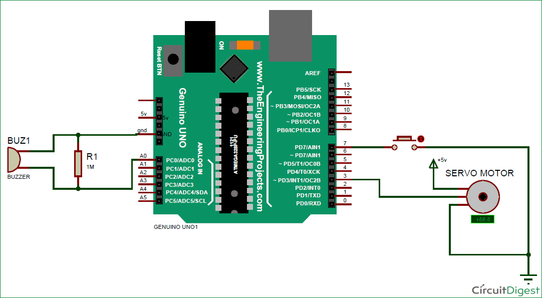
The circuit Diagram of this Knocking Pattern Detector is very simple which contains Arduino for controlling whole the process of the project, push button, buzzer, and Servo Motor. Arduino controls the complete processes like taking password form Buzzer or Sensor, comparing patterns, driving Servo for open and close the gate and save the pattern to Arduino.
The push button is directly connected to pin D7 of Arduino with respect to ground. And a buzzer is connected at analog pin A0 of Arduino with respect to ground and with a 1M resistance between A0 and ground also. A Servo motor is also connected to PWM pin D3 of Arduino.
Feeding Knocking Pattern in Arduino:
In this circuit, we have used Buzzer or Peizo Sensor to take knock input pattern in the system. Here we are using a push button to allow to take input from the sensor and also save that into the Arduino. This system is designed by taking idea from Morse code pattern but not exactly similar with that.
Here we have used a card board box for demonstration. To take input we knock over the board after pressing push button. Here we have knocked by keeping a time period in mind that is 500ms. This 500ms is because we have fixed it in code and input pattern is depending upon it. This 500ms time period will define the input was 1 or 0. Check the code below to understand this thing.
When we knock it, Arduino starts monitoring the time of the first knock to second knock and put that in an array. Here in this system, we are taking 6 knocks. It means we will get 5 time periods.
Now we check the time period one by one. First, we check time period between first knock and second knock if the time difference between these less the 500ms then it will be 0 and if greater than 500ms it will be 1 and it will be saved into a variable. Now after it, we check time period between second knock and third knock and so on.
Finally, we will get 5 digit output in 0 and 1 format (binary).
Working Explanation:
Working of Knock based Smart Lock Project is simple. First we have to save a pattern in the system. So we have to press and hold push button until we knock 6 times. Here in this project, I have used 6 knocks but the user may change it as they want. After six times knock, Arduino find the knock pattern and save that in EEPROM. Now after saving the input pattern, press and immediately released the push button for taking input from the sensor to Arduino to open the lock. Now we have to knock 6 times. After it, Arduino decodes it and compares with saved pattern. If a match occurs then Arduino open the gate by driving servo motor.
Note: when we press or press and hold the push button Arduino start a 10 seconds timer to take all 6 knock. Means user need to knock within this 10 seconds time. And the user may open Serial monitor to see the log.
Programming Explanation:
In a program first of all we include the header file and defines input and output pin and define the macro and declared variables as you can see in the Full Code in code section below.
After this, in setup function, we give direction to defined pin and initiate servo motor.
void setup()
{
  pinMode(sw, INPUT_PULLUP);
  myServo.attach(servoPin);
  myServo.write(180);
  Serial.begin(9600);
}
After it, we take input and save the input pattern or knock time in an array.
void loop()
{
   int i=0;
   if(digitalRead(sw) == LOW)
   {
      Serial.println("Start");
      delay(1000);
      long stt= millis();
      while(millis()<(stt+patternInputTime))
      {
        int temp=analogRead(A0);
        if(temp>sensitivity && flag==0 && i<=patternLenth)
        {
.... .
..... ....
After it, we decode the input pattern
      for(int i=0;i<patternLenth;i++)
      {
         knok=1;
         if(slot[i+1]-slot[i] <500 )
            pattern[i]=0;
         else
            pattern[i]=1;
         Serial.println(pattern[i]);
      }
And then save if push button is still pressed
      if(digitalRead(sw) == 0)
      {
         for(int i=0;i<patternLenth;i++)
            EEPROM.write(i,pattern[i]);
         while(digitalRead(sw) == 0);
      }
And if push button is not still pressed then Arduino will compare input decoded pattern with saved pattern.
      else
      {
         if(knok == 1)
         {
            for(int i=0;i<patternLenth;i++)
            {
               if(pattern[i] == EEPROM.read(i))
               {
                  Serial.println(acceptFlag++);
               }

               else
               {
                    Serial.println("Break");
                    break;
               }
            }
         }
If any password matched, then Servo open the gate otherwise nothing happened but the user may see result over serial monitor.
         Serial.println(acceptFlag);
         if(acceptFlag >=  patternLenth-1)
         {
             Serial.println(" Accepted");
             myServo.write(openGate);
             delay(5000);
             myServo.write(closeGate);
         }
         else
            Serial.println("Rejected");
      }
You can check the complete code below with a demo Video.
Read more: Smart Knock Detecting Door Lock using Arduino
- What components are required to build this project?
The project requires an Arduino Uno, Push Button, Buzzer, 1M Resistor, Power, Connecting wires, Box, and Servo Motor. - How does the system detect the knocking pattern?
The system uses a buzzer or piezo sensor connected to analog pin A0 to monitor knock time periods and convert them into binary data. - What is the time threshold used to distinguish between 0 and 1?
A time period of 500ms is fixed in the code; differences less than 500ms represent 0, while greater differences represent 1. - How many knocks are needed to save or enter the password?
The system is designed to take 6 knocks, which results in 5 time periods being analyzed to form the pattern. - Can the user change the number of knocks required?
Yes, the article states that while 6 knocks are used, the user may change this number as they want. - What happens if the push button is held down during the process?
Holding the push button initiates a 10-second timer to allow the user to knock 6 times for saving or entering the pattern. - How does the Arduino verify the entered pattern?
After decoding the input, the Arduino compares the resulting binary array with the pattern previously saved in the EEPROM. - What action does the servo motor take if the pattern matches?
If the pattern matches, the Arduino drives the servo motor to the open position for 5 seconds before closing it again.
