Summary of Sinewave Inverter Circuit Using Arduino
The article explains building a basic single-phase and a 3-phase sinewave inverter using Arduino PWM (SPWM) signals. It covers using Arduino-generated PWM at ~200 Hz to modulate power transistor/IGBT stages via divider networks and diodes, notes IC4047 use or bypass, transformer interaction, an IRS2330 bridge driver for 3-phase control, and practical tips on component choices, voltage regulation, and current sensing.
Parts used in the Sinewave Inverter Project:
- Arduino Uno
- IC 4047 (astable/multivibrator)
- IC 4049 (six NOT gates)
- IRS2330 bridge driver IC
- Power BJ transistors (or IGBTs as alternatives)
- 6 IGBTs (for 3-phase bridge)
- Transformer (inverter transformer)
- Resistors (including 1 ohm current sensing resistor)
- 1K preset (for over current limit adjustment)
- Potentiometer P1
- Capacitor C1
- Reverse biased diodes (for PWM negative pulse gating)
- Voltage regulator components for steady 9V supply (including T1 and associated parts)
- Voltage divider networks
The article demonstrates the construction of a basic sinewave inverter circuit utilizing PWM signal from an Arduino Uno, also exploring a sinewave 3 phase inverter with Arduino input. Mr. Raju Visswanath was the one who requested the concept.
Technical Specifications
UPDATE:
Please also refer to this article which explains how to build a simple pure sine wave inverter circuit using Arduino using SPWM……Full Program code also included….
The Design
The article details the construction of a basic sinewave inverter circuit using PWM signal from an Arduino Uno, and also explores a sinewave 3 phase inverter with input from the same Arduino. Mr. Raju Visshwanath requested the concept.
 This frequency drives the two power BJ transistor stages alternately at the specified frequency rate.
The transistors could be replaced with IGBTs for getting better efficiency, but mosfets should be avoided as these may require special attention while designing the PCB, and additional buffer BJT stages to prevent heating up of the mosfets from possible hidden stray inductance or harmonics.
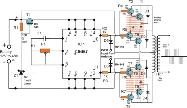
Circuit Operation
P1 and C1 in the diagram determine the astable’s frequency, and adjusting P1 with a frequency meter can change it to match the desired inverter frequency.
If the inverter’s voltage falls under 15V, T1 and its associated components for keeping a steady 9V for the IC 4047 can be taken out. However, it is recommended to test higher voltages of up to 60V in order to create a more effective and smaller inverter design.
The PWM signal from the Arduino is distributed across voltage divider networks on both IC outputs, with reverse biased diodes used to allow only negative PWM pulses to affect power stages and effectively control their conduction.
Because of the PWM chopping effect, the current is adjusted within the transformer to align with the desired PWM sinewave, ultimately boosting the mains voltage at the transformer’s secondary.
The Arduino’s PWM frequency should be around 200 Hz. If a 50 Hz totem pole is set up on the Arduino, the IC4047 can be eliminated and the signals can be directly linked to the left side terminals of R2 and R3.
Circuit for a 3 Phase Inverter using Arduino
The pair of diagrams provided depict the setup of a 3 phase PWM controlled inverter that utilizes an Arduino for operation.
Six NOT gates are used from the IC 4049 in connecting the original diagram. This process divides the Arduino PWM signals into paired high/low logic signals to ensure compatibility with the supplied PWMs for the bridge 3 phase inverter driver IC IRS2330.
The second diagram in the suggested Arduino PWM, 3 phase inverter design consists of the bridge driver stage using the IC IRS2330 chip.
The HIN and LIN inputs of the IC receive Arduino PWM signals, go through NOT gates, and command the output bridge network consisting of 6 IGBTs, which in turn control the connected load via their three outputs.
The 1K preset is employed to modify the over current limit of the inverter by linking it to the shutdown pin of the I, the 1 ohm sensing resistor can be reduced if a higher current is required for the inverter.
Source : Sinewave Inverter Circuit Using Arduino
- What microcontroller is used to generate the PWM for the inverter?
The Arduino Uno is used to generate the PWM signals for the inverter. - Can the IC4047 be omitted in the single-phase design?
Yes, if a 50 Hz totem pole is set up on the Arduino, the IC4047 can be eliminated and signals linked directly to R2 and R3 terminals. - What frequency should the Arduino PWM be set to?
The Arduino PWM frequency should be around 200 Hz according to the article. - What components can replace power BJ transistors for better efficiency?
IGBTs can replace the BJ transistors for better efficiency. - Should MOSFETs be used for the power stage?
The article advises avoiding mosfets because they may require special PCB design and additional buffer BJT stages to prevent heating from stray inductance or harmonics. - What is the role of P1 and C1 in the circuit?
P1 and C1 determine the astable frequency of the IC4047, and adjusting P1 with a frequency meter changes the inverter frequency. - How are Arduino PWM signals conditioned before driving the bridge driver?
Arduino PWM signals pass through NOT gates from IC4049 to create paired high/low logic signals compatible with the IRS2330 driver inputs. - How does the inverter control current through the transformer?
Due to PWM chopping, current in the transformer is adjusted to match the PWM sinewave, which then boosts the mains voltage at the secondary. - What is the function of the 1K preset and 1 ohm resistor in the 3-phase design?
The 1K preset adjusts the inverter over current limit via the shutdown pin, and the 1 ohm sensing resistor provides current sensing and can be reduced for higher current.