
Summary of SIMPLE STM32 FREQUENCY METER HANDLES UP TO 30MHZ WITH EASE
Summary: [mircemk] upgraded a DIY frequency counter from an Arduino to an STM32F103 (C6 or C8) board, extending its measurable range from 6 MHz to 30 MHz. The build uses LED 7-segment displays for readout and a single input capacitor accepting 0.5–3 V signals. The design is simple and inexpensive, suitable for HF radio work, but benefits from calibration and could gain versatility with a more advanced input stage.
Parts used in the STM32 frequency meter:
- STM32F103C6 or STM32F103C8 development board
- LED 7-segment displays
- Single input capacitor
- Wiring and connectors
- Power supply (for the development board and displays)
- Optional enclosure or mounting hardware
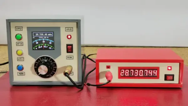
The project is relatively simple to construct, with an STM32F103C6 or C8 development board used as the brains of the operation. It’s paired with old-school LED 7-segment displays for showing the measured frequency. Just one capacitor is used as input circuitry for the microcontroller, which can accept signals from 0.5 to 3V in amplitude. [mircemk] notes that the circuit would be more versatile with a more advanced input circuit to allow it to work with a wider range of signals.
It’s probably not the most accurate frequency counter out there, and you’d probably want to calibrate it using a known-good frequency source once you’ve built it. Regardless, it’s a cheap way to get one on your desk, and a great way to learn about measuring and working with time-varying signals. You might like to tke a look at the earlier build from [mircemk] for further inspiration. Video after the break.
Source: SIMPLE STM32 FREQUENCY METER HANDLES UP TO 30MHZ WITH EASE
- What microcontroller is used in the project?
The project uses an STM32F103C6 or STM32F103C8 development board as the microcontroller. - What frequency range can this meter measure?
The meter can measure frequencies up to 30 MHz. - What displays are used to show the measured frequency?
Old-school LED 7-segment displays are used for readout. - What input circuitry is required?
The design uses just one input capacitor as the input circuitry for the microcontroller. - What signal amplitude range does the input accept?
The microcontroller input can accept signals from 0.5 to 3 V in amplitude. - Is the meter highly accurate out of the box?
It is probably not the most accurate and should be calibrated using a known-good frequency source. - Would a more advanced input circuit be beneficial?
Yes, a more advanced input circuit would make the meter more versatile and allow it to work with a wider range of signals. - Is this project suitable for HF radio work?
Yes, the extended 30 MHz range makes it a useful tool for working with HF radio frequencies.
