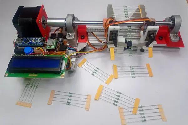
Summary of Machine for Cutting Resistor Reels Utilizing Arduino Technology
This project describes an open-source Arduino-powered machine that automatically feeds, counts, and cuts component reels (resistors, diodes, etc.) into fixed-length segments using a NEMA17-driven feeding system, MOC7811 optical feedback, and dual servos for cutting. Designed for easy 3D-printed assembly and aluminum-extrusion framing, it improves reliability over prior designs by adding sensor feedback, simpler servo-based cutters, and editable CAD, schematics, and Arduino Nano code.
Parts used in the Resistor Reel Cutting Machine:
- Aluminum Extrusion Profile 20x40 6T Slot
- Smooth Shaft Rod 8mm Diameter
- Threaded Rod 8mm Diameter
- Nema17 motor Coupling for 8mm soft shaft
- Flanged Ball Bearing 8mm bore – 2pcs
- Pillow Block Mount 8mm bore – 2pcs
- Cast Corner Bracket for 2020 Aluminum Extrusion – 4pcs
- Sliding T nut for 2020 Aluminum Extrusion – 20 pcs
- M4 6mm Socket Screws for T nut – 20 pcs
- Timing Belt for pully
- Nema17 Stepper Motor
- MG90S Servo Motor with Metal Gear
- Arduino Nano
- 16x2 LCD Screen (with I2C module)
- A4988 Stepper Motor Driver module
- MOC7811 opto-coupler sensor
- 12V 2A DC adapter
- Push buttons
- 50V 100uF electrolytic capacitor
- Connecting Wires and perf board
- 3D-printed parts (motor mount, feeding roller, reel guide, blade mounts)
Introduction
In advanced electronics PCB assembly lines, pick and place machines are typically used to retrieve components from an SMD reel and position them on a PCB. However, this becomes impractical for medium-scale production or when employing THT (through-hole type) components on your PCB. This situation is particularly relevant in cost-effective board assemblies, such as LED drivers and transformer less power supplies. To enhance the efficiency of this assembly process and facilitate the preparation of the necessary component quantities, we have developed the Arduino-based Resistor Cutting reels Machine.
This machine is versatile and capable of managing various types of component reels, including those containing resistors, diodes, and similar items. It can precisely extract a specified quantity of components from a reel and then cut them to the desired amount. Consequently, it enables us to efficiently divide an entire reel into smaller, precisely measured segments.
Fundamental Mechanism and Operation
When I embarked on this project, I came across an existing project on the internet titled “Resistor Cutting Robot” by Pablo. While I found this project quite impressive, my goal was to enhance its reliability and simplify the construction process for a wider audience. To achieve this, I incorporated the following key improvements:
- The aim is to create a machine that is easily constructible, allowing individuals with access to a 3D printer to assemble it without the requirement for an extensive array of power tools.
- Enhance the precision and dependability of the machine by incorporating an MOC7811 optoisolator sensor, serving as a feedback mechanism for our Arduino. This addition enables us to precisely monitor the quantity of components pushed during each operation.
- Substitute the wooden base with readily accessible aluminum extrusion from the market, thereby enhancing the design’s durability and user-friendliness.
- Modify the cutting mechanism by transitioning from stepper motors to servo motors, simplifying the design and making it more straightforward to construct.
- Enable universal access to the entire design by offering it as open-source, providing editable CAD files, schematics, and the Arduino code for all to use.
Materials Needed for Constructing a Resistor Reel Cutting Machine
As previously mentioned, the concept behind this construction was to keep the materials and tools required as straightforward and accessible as possible. You will exclusively require the following components to construct your resistor cutting machine.
Mechanical Elements
- Aluminum Extrusion Profile 20×40 6T Slot
- Smooth Shaft Rod 8mm Diameter
- Threaded Rod 8mm Diameter
- Nema17 motor Coupling for 8mm soft shaft
- Flanged Ball Bearing 8mm bore – 2pcs
- Pillow Block Mount 8mm bore – 2pcs
- Cast Corner Bracket for 2020 Aluminum Extrusion – 4pcs
- Sliding T nut for 2020 Aluminum Extrusion – 20 pcs
- M4 6mm Socket Screws for T nut – 20 pcs
- Timing Belt for pully
Electrical Components
- Nema17 Stepper Motor
- MG90S Servo Motor with Metal Gear
- Arduino Nano
- 16×2 LCD Screen
- A4988 Stepper Motor Driver module
- MOC7811 opto-coupler sensor
- 12V 2A DC adapter
- Push buttons
- 50V 100uf electrolytic capacitor
- Connecting Wires and perf board
The Mechanical Assembly of the Arduino-Based Resistor Cutting Machine
The entire mechanical assembly for the machine is divided into smaller sections and is elaborated upon below.
Driving Mechanism:
The primary driving motor for our machine is the NEMA17 stepper motor. If you are unfamiliar with working with NEMA17 stepper motors, you can refer to this article that provides a basic guide on using NEMA17 with an A4988 stepper motor driver module. The NEMA17 motor is linked to an 8mm flexible shaft through a coupler, as illustrated below. This setup ensures that when the motor rotates, the flexible shaft also rotates in tandem.
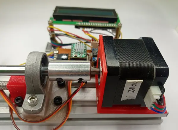
We opted for a stepper motor due to its ability to provide consistent step control throughout the machine’s operation, resulting in uniform feeding. As depicted in the image above, we’ve utilized a 3D-printed motor mount to secure the NEMA17 motor firmly to the aluminum extrusion bar.
Feeding Mechanism:
Moving on to the subsequent phase of the machine, we have the feeding system. This is accomplished through the utilization of a flexible shaft, a threaded rod, a pair of pillow blocks, and feeding rollers, as demonstrated below.
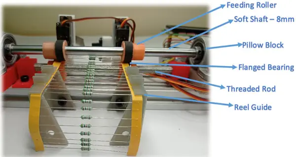
Feeding Roller: This component is a 3D-printed part with a timing belt adhered to it. The rubber surface of the timing belt offers sufficient friction and pressure to ensure consistent advancement of the reel strip.
Flexible Shaft: The flexible shaft is connected to the stepper motor, and the feeding roller is securely fastened onto the flexible shaft. This arrangement allows for the adjustment of the spacing between the feeding rollers as needed, and the roller rotates in sync with the stepper motor.
Pillow Blocks: To ensure that the flexible shaft remains parallel to the aluminum extrusion, we have incorporated two pillow blocks, one on each side of the flexible shaft. Additionally, these two blocks assist in adjusting the gap between the flexible shaft and the threaded rod, thereby allowing control over the pressure applied by the rollers to the resistor reel.
Threaded Rod and Flanged Bearing: We’ve employed an 8mm threaded rod with a flanged bearing positioned beneath the flexible shaft. These flanged bearings serve the dual purpose of securing the resistor reel in position and enabling free rotation as the roller moves, facilitating the feeding of the reel into the cutting section. Although the flanged bearing might not be entirely visible in the image above, you can refer to the video linked at the bottom of this page for a clearer comprehension.
Reel Guide: The reel guide consists of a pair of 3D-printed components affixed to the aluminum extrusion. As depicted in the image, the resistor reel is directed into the rollers via this reel guide, ensuring that the reel consistently enters at a right angle to the feeding rollers.
Counting and Feedback System:
While I had carefully designed the feeding mechanism to the best of my ability, there were occasional occurrences of resistor reel slippage, resulting in uneven feeding. Therefore, I found it necessary to incorporate a sensor to tally the number of resistors being fed into the machine before the cutting process. This addition provides valuable feedback, allowing us to ensure that the operation runs seamlessly.
In the depicted illustration, you can observe our installation of an MOC7811 optocoupler sensor designed to keep track of the resistors or diodes being dispensed from the feeding mechanism. It’s worth noting that we have adjusted and adapted the distance between the sensor’s transmitter and receiver to accommodate the entire strip’s passage through the sensor.
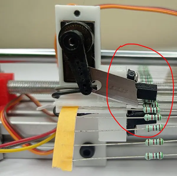
Cutting Mechanism:
The final component of the machine is the Cutting Mechanism, which operates using two servo motors with blades affixed to their horns, as demonstrated below.
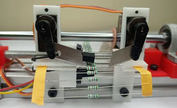
I maintain my belief that there is ample room for enhancement in this particular aspect, particularly concerning the method of mounting the blades. I welcome any suggestions or input from readers who may have better alternatives. However, it’s worth noting that employing two servos does offer an advantage, as it allows for independent control of the blades. We can fine-tune the servo angles individually to maintain close proximity of the blades to the strip and ensure they move at an equal speed and synchronized timing, thus guaranteeing a consistent cut on both sides.
Schematic for the Arduino-Operated Resistor Reel Cutting Machine
Below is the comprehensive circuit diagram for our homemade Arduino-based resistor cutting machine:
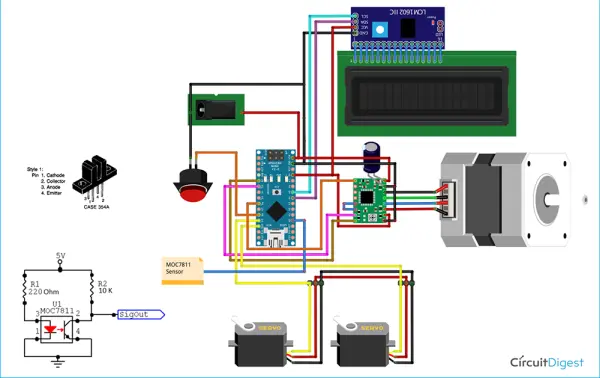
As depicted, the circuit is quite straightforward. We’ve employed a 12V 2A adapter to supply power to the entire setup. The onboard 5V regulator on the Arduino Nano is utilized to energize the MOC7811 sensor and the servo motor, with power sourced from the 5V pin on the Arduino board. The connection between the 16×2 LCD and the Arduino Nano is facilitated by an I2C module, which is connected to the I2C pins on the Arduino, specifically pins A4 and A5.
In the provided schematics, we’ve presented the MOC7811 circuit separately because Fritzing lacks a dedicated component for it. The 220-ohm resistor serves the purpose of regulating the current passing through the photodiode, while the 10K resistor acts as a pull-up resistor for the sensor’s output pin. When an object is detected, the Sigout pin registers a voltage of 0V; otherwise, it reads 5V. This pin is connected to an analog pin on the Arduino to monitor the presence of any components passing through the sensor.

As evident from the image above, I have assembled the entire circuit on a custom PCB (printed circuit board), incorporating header pins for connecting the stepper motor, servo motors, LCD display, and sensor. Subsequently, I secured the board and the LCD display firmly in position using L-clamps and a selection of screws, as illustrated in the image below:
Programming the Arduino for the Resistor Reel Cutting Machine
The comprehensive code for the resistor cutting machine is available at the end of this page. In this section, I will elucidate the crucial sections of the code. The entire code was developed and verified for Arduino Nano utilizing the old bootloader. If you have any queries, feel free to post them in the comment section below.
Within the void setup function, we initiate by specifying the characteristics of input and output pins. It’s noteworthy that we’ve designated the push button pin as an input with pull-up enabled. Consequently, when the button is pressed, the digital read will yield a zero.
 // Sets pinmodes
  pinMode(stepPin,OUTPUT);
  pinMode(dirPin,OUTPUT);
  pinMode(enablePin,OUTPUT);
  pinMode(pushButton,INPUT_PULLUP);
Subsequently, we position our servo motors to their initial state. This action retracts the blades from the feeding path, allowing us to load the resistor reel into position. Adjustments to the values of left_pos and right_pos may be necessary depending on your specific needs.
//Move servo to default position
  left_servo.attach(9);  // attaches the servo on pin 9 to the servo object
  left_servo.write(left_pos);
  delay (1000);
  right_servo.attach(10); //attaches the servo on pin 10 to the servo object
  right_servo.write(right_pos);
  delay(1000);
After completing the initialization process, we’ve employed a while loop to keep the program in a holding state while continually monitoring the push button’s status. Only when the push button is pressed will the code progress further. This approach provides the user with an opportunity to prepare the machine before it commences its operation.
  while(digitalRead (pushButton) ==HIGH) //Wait here till this the button is long pressed
  {
    }
We’ve implemented a function named “step_forward()” to advance the stepper motor by a single step. During this process, it increments a variable named “step_count” and simultaneously monitors for any issues in the resistor reel feed. Specifically, as the motor rotates, the resistor reel should progress forward, and the MOC7811 sensor should be activated by the resistor passing through it. If the sensor fails to detect any components while the stepper motor is in motion, it signifies a fault, prompting us to halt the process. This fault condition is addressed within the “else” loop in the code snippet below.
void step_forward()
{
  if (Step_count < Max_steps_before_fault)
  {
    digitalWrite(dirPin,HIGH); // Enables the motor to move in a particular direction
    digitalWrite(stepPin,LOW);
    delayMicroseconds(1000);
    digitalWrite(stepPin,HIGH);
    delayMicroseconds(1000);
    Step_count++;
  }
  else
  {
  lcd.clear();
  lcd.setCursor(3,0);
  lcd.print("Step Fault");
  digitalWrite(enablePin,HIGH);    //Diable Stepper Motor
  while (1);
    }
}
Continuing further, we have introduced another function named “chop().” Its purpose is to engage the servo motors and execute the cutting of the resistor reel once the desired number of components have been dispensed. It’s crucial to ensure that both servo motors move simultaneously and cover the same distance. To achieve this synchronization, we have employed two “for” loops, as demonstrated below.
void chop()
{
  for (int steps = 0; steps <= 120; steps += 1) {
    left_pos = 170-steps; //moves servo from 160 to 60
    right_pos = 60+steps; //moves servo from 60 to 160
    left_servo.write(left_pos);
    right_servo.write(right_pos);
    delay(3);
  }
  delay(100);
  for (int steps = 0; steps <= 120; steps += 1) {
    left_pos = 60+steps; //moves servo from 60 to 160
    right_pos = 170-steps; //moves servo from 160 to 60
    left_servo.write(left_pos);
    right_servo.write(right_pos);
    delay(3);
  }
}
In the “void loop,” there isn’t much to manage. Our primary task is to continually turn the stepper motor until the sensor detects the presence of a resistor. To maintain a controlled pace, we’ve inserted a 20-millisecond delay between each motor step.
//ROTATE the STEPPER TILL WE FIND A RESISTOR
  if (sensorValue<500)//if no resistor is found
    {
     step_forward();
     delay(20);
    }
In case the sensor is obstructed by a resistor, we acknowledge this by increasing the “Resistor_count” variable and subsequently continue with the step-forward operation.
 //IF RESISTOR DETECTED - Step forward till the resistor is passed
  if (sensorValue>500)//resistor detected
    {
     Resistor_count = Resistor_count+1;
     Step_count=0;
     while (sensorValue>500)//while resistor is still under sensor
      {
        step_forward();
        sensorValue = analogRead(A0);
        delay(20);
      }
    }
When the machine has dispensed the necessary quantity of resistors, it’s time to cut the resistor reel, and the following code accomplishes this task precisely. You have the flexibility to adjust the “chop_count” variable according to your desired number of resistors for the cutting process.
 //IF COUNT REACHED
   if (Resistor_count==Chop_Count)
   {
    step_forward();step_forward();step_forward();step_forward(); step_forward();step_forward(); //few steps forward to cut exactly in the middle of two resitors
     chop();
     Total_cut++;
     Resistor_count=0;
     delay(200);
   }
The Arduino-Powered Resistor Cutting Machine in Operation
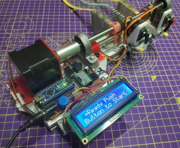
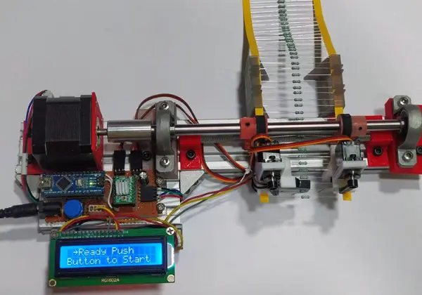
Operating the machine is quite straightforward. Simply power it on, and the machine will go through its initialization process. Afterward, you’ll be prompted to press a button. Prior to doing so, ensure you have your resistor or any other component reel with tape ready to feed into the machine. During this stage, the stepper motor will be deactivated, allowing you to manually adjust the motor’s position to align the reel correctly, as illustrated in the image below.
Following this, simply press the start button, and our machine will spring into action. If you’d like to observe the entire operation in action, you can watch the comprehensive demonstration video linked at the bottom of the page.
To wrap up this article, I’m reaching its conclusion. I trust you found it enjoyable and gained some valuable insights. If you have any suggestions or innovative ideas for improvement, please don’t hesitate to share them in the comment section; your feedback is highly appreciated. Additionally, if you have any questions about this project or similar endeavors, feel free to explore our forums for further discussions.
Code
/* Resistor cutting CNC Machine
 *  Servo is connected to PWM pins 9 and 10
 *  A4988 Stepper Driver Enable, Step and Dir pincs connected to D6, D3 and D4 resp.
 *  I2C LCD dipslay connected to A4 and A5
 *  MOC7811 is connected to A0
 *  Push Button Connected to D8
*/
#include <Servo.h>
#include <Wire.h>
#include <LiquidCrystal_I2C.h>
// defines pins numbers
const int stepPin = 3;
const int dirPin = 4;
const int enablePin = 6;
const int pushButton = 8;

const int  Max_steps_before_fault=25;
const int Job_Complete = 20;

int Chop_Count = 0;

int Resistor_count = -1;
int Step_count =0;
int Total_cut = 0;

int left_pos = 170;    // variable to store the servo position
int right_pos =60;

Servo left_servo;
Servo right_servo;

LiquidCrystal_I2C lcd(0x27, 16, 2);
void setup() {

    // Sets pinmodes
  pinMode(stepPin,OUTPUT);
  pinMode(dirPin,OUTPUT);
  pinMode(enablePin,OUTPUT);
  pinMode(pushButton,INPUT_PULLUP);

  //Diable Stepper Motor
  digitalWrite(enablePin,HIGH);
  Serial.begin(9600);// initialize serial communication at 9600 bits per second:
  lcd.begin ();
  lcd.backlight();

  //Move servo to default position
  left_servo.attach(9);  // attaches the servo on pin 9 to the servo object
  left_servo.write(left_pos);
  delay (1000);
  right_servo.attach(10); //attaches the servo on pin 10 to the servo object
  right_servo.write(right_pos);
  delay(1000);

  if (digitalRead (pushButton) ==HIGH)
  Chop_Count = 5;
  else
  Chop_Count =20;
  lcd.clear();
  lcd.setCursor(1,0);
  lcd.print("Resistor Cutter");
  lcd.setCursor(4,1);
  lcd.print("Mode Set");
  delay(3000);

  lcd.clear();
  lcd.setCursor(1,0);
  lcd.print(" ~Chop "); lcd.print(Chop_Count); lcd.print(" pcs");
  lcd.setCursor(0,1);
  lcd.print(" Press to Start");

  while(digitalRead (pushButton) ==HIGH) //Wait here till this the button is long pressed
  {
    }

//Enable Stepper Motor
  digitalWrite(enablePin,LOW);
  lcd.clear();
  lcd.setCursor(0,0);
  lcd.print("R_Count:  /5"); //display the count in 8th place
  lcd.setCursor(0,1);
  lcd.print("Job:  /20 ");//display number of pcs at 4 and Steps at 14
  delay (1000);
}
void step_forward()
{
  if (Step_count < Max_steps_before_fault)
  {
    digitalWrite(dirPin,HIGH); // Enables the motor to move in a particular direction
    digitalWrite(stepPin,LOW);
    delayMicroseconds(1000);
    digitalWrite(stepPin,HIGH);
    delayMicroseconds(1000);
    Step_count++;
  }
  else
  {
  lcd.clear();
  lcd.setCursor(3,0);
  lcd.print("Step Fault");
  digitalWrite(enablePin,HIGH);    //Diable Stepper Motor
  while (1);
    }
}
void chop()
{

  for (int steps = 0; steps <= 120; steps += 1) {
    left_pos = 170-steps; //moves servo from 160 to 60
    right_pos = 60+steps; //moves servo from 60 to 160
    left_servo.write(left_pos);
    right_servo.write(right_pos);
    delay(3);
  }
  delay(100);

  for (int steps = 0; steps <= 120; steps += 1) {
    left_pos = 60+steps; //moves servo from 60 to 160
    right_pos = 170-steps; //moves servo from 160 to 60
    left_servo.write(left_pos);
    right_servo.write(right_pos);
    delay(3);
  }
}

void loop() {

  lcd.setCursor(14,1);
  lcd.print(Step_count);//display  Steps at 14
  lcd.setCursor(8,0);
  lcd.print(Resistor_count+1); //display the count in 8th place
  lcd.setCursor(4,1);
  lcd.print(Total_cut);//display  pcs at 4

  int sensorValue = analogRead(A0); // read the input on analog pin 0 from MOC7811

  //ROTATE the STEPPER TILL WE FIND A RESISTOR
  if (sensorValue<500)//if no resistor is found
    {
     step_forward();
     delay(20);
    }

  //IF RESISTOR DETECTED - Step forward till the resistor is passed
  if (sensorValue>500)//resistor detected
    {
     Resistor_count = Resistor_count+1;
     Step_count=0;
     while (sensorValue>500)//while resistor is still under sensor
      {
        step_forward();
        sensorValue = analogRead(A0);
        delay(20);
      }
    }

   //IF COUNT REACHED
   if (Resistor_count==Chop_Count)
   {
    step_forward();step_forward();step_forward();step_forward(); step_forward();step_forward(); //few steps forward to cut exactly in the middle of two resitors
     chop();
     Total_cut++;
     Resistor_count=0;
     delay(200);
   }

   //Press the button for emergency stop
   if (digitalRead (pushButton) ==LOW)
   {
      lcd.clear();
      lcd.setCursor(0,0);
      lcd.print(" Emergency Stop");
      digitalWrite(enablePin,HIGH);    //Diable Stepper Motor
      while (1);
    }

   //Stop the machine after 20 cuts
      if (Total_cut == Job_Complete)
   {
      lcd.clear();
      lcd.setCursor(0,0);
      lcd.print(" Job Completed ");
      digitalWrite(enablePin,HIGH);    //Diable Stepper Motor
      while (1);
    }
- What is the main purpose of the machine?
The machine feeds, counts, and cuts components from reels (resistors, diodes) into specified quantities and segments. - Can the design be built without advanced power tools?
Yes. The design aims to be easily constructible with access to a 3D printer and basic tools. - How does the machine detect components for counting?
It uses an MOC7811 optocoupler sensor connected to an Arduino analog input to detect components passing through. - What drives the feeding mechanism?
A NEMA17 stepper motor coupled to an 8mm flexible shaft and feeding rollers advances the reel. - How is the cutting action implemented?
Two MG90S servo motors with blades on their horns simultaneously move to cut the reel. - Which microcontroller and display are used?
An Arduino Nano controls the machine and a 16x2 LCD with I2C displays status. - What stepper driver is required?
An A4988 stepper motor driver module is used to control the NEMA17 stepper. - How is power supplied to the system?
A 12V 2A DC adapter powers the setup; the Arduino Nano onboard regulator supplies 5V to servos and the sensor. - Does the firmware include fault detection?
Yes. The code monitors step counts and sensor feedback; exceeding Max_steps_before_fault triggers a step fault and stops the motor. - Is the project open-source and editable?
Yes. The author provides editable CAD files, schematics, and Arduino code as open-source resources.