
Summary of Simple Ipod Controller using an Arduino
This Instructable demonstrates how to interface an Arduino with an iPod using the serial protocol (Mode 2) to send basic commands. It details the necessary hardware setup, specifically focusing on a voltage divider to protect the iPod from the Arduino's 5V signal. The project uses push buttons to trigger specific actions via a defined message format involving headers, command words, and checksums.
Parts used in the iPod Serial Controller:
- 1x Arduino
- 4x Push Buttons
- 4x 10k ohm resistor
- 3x 1k ohm resistor
- 1x 500k equivalent ohm resistor
- 1x ipod breakout
This instructable will help you understand the iPod serial protocol, and how to send commands to an iPod using an Arduino. This instructable is only meant to show the basics of the protocol and is by no means complete. I only had enough hardware space for 4 buttons, and the software reflects that.

Hardware Needed :
1x Arduino
4x Push Buttons
4x 10k ohm resistor
3x 1k ohm resistor
1x 500k equivalent ohm resistor
1x ipod breakout
References for this ‘Ible
pinouts.ru
arduino forums big thanks to user EASTY, who’s code I built off.
cornell students
adrian game
Step 1: Hardware
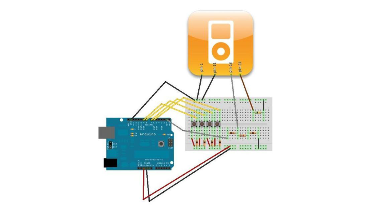
The most important part of this setup is the voltage divider . The iPod Rx only expects 3.3v, so anything more than that (like the Arduino’s 5v TX) could hurt your iPod. The voltage divider is a safe way to ensure that when the Arduino sends a 5v HIGH, your iPod only gets hit with a 3.3v HIGH.
The divider is accomplished in two steps. First tie the Arduino TX (pin1) to a 1k ohm resistor. Second, on the other end of the resistor attach iPod pin 13 (RX) AND two 1k ohm resistors (in series).
The 500k Ohm resistor attached to pin 21 tells the ipod that you will be using a serial communication (see reference ).
Both iPod pins 1 and 11 should be grounded to the arduino. (To the nit pickers, I know the references state different things about pin 11, but grounding it seems to have no effect on this project.)
The rest of the hardware should be pretty straight forward, if you’d like more information on push buttons there is a tutorial on the arduino website .
Step 2: The Ipod Serial Protocol (mode 2)
For a more detailed description, see this reference . For a quick and dirty version, keep reading.
The iPod can communicate in four different modes, this instructable uses Mode Two: iPod Remote. Other modes include Advance iPod Mode and Voice Recorder Mode. Messages are sent via the arduino’s uart, with a baud rate of 19200 . Each message has the same format, and as a result, most Mode Two messages are 7 bytes long.
All messages start with a header that is 2 bytes long. This header is always 0xff, 0x55. Next comes the message length . This value tells the iPod how many more bytes to read. Next comes iPod mode . We always operate in mode 2 so this doesn’t change in our code. The next two bytes are the command word. The reference above has a list of all the known command words in detail. The command word can actually be more than 2 bytes, but this software only supports 2 byte commands. Next comes the parameters , these are used in Mode Four only, so this project keeps this value set to 0x00. It is also omitted from the command. Finally, the checksum is calculated for error checking. The checksum is equal to the sum of the length , mode , command and parameters bitwise anded with 0xff (to mask off 8 bits) and subtracted from 0x100.
4x Push Buttons
4x 10k ohm resistor
For more detail: Simple Ipod Controller using an Arduino
- What is the primary purpose of this project?
To understand the iPod serial protocol and send commands to an iPod using an Arduino. - Why is a voltage divider needed in this setup?
The iPod Rx expects 3.3v, so the divider ensures the Arduino's 5v TX does not damage the iPod. - How is the voltage divider constructed?
Tie Arduino TX to a 1k ohm resistor, then attach iPod pin 13 RX and two series 1k ohm resistors to the other end. - What function does the 500k ohm resistor serve?
It tells the iPod that serial communication will be used. - Which iPod pins should be grounded?
Both iPod pins 1 and 11 should be grounded to the arduino. - What baud rate is used for communication?
Messages are sent via the arduino uart at a baud rate of 19200. - What mode does this project utilize?
The project uses Mode Two, known as iPod Remote. - How many bytes long are most Mode Two messages?
Most Mode Two messages are 7 bytes long. - What values start every message header?
All messages start with a 2 byte header of 0xff and 0x55. - How is the checksum calculated?
It is the sum of length, mode, command, and parameters bitwise anded with 0xff, subtracted from 0x100.
