Summary of Simple IoT Remote Switch With MQTT and ESP8266
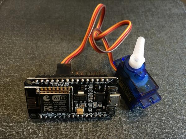
This article details a proof-of-concept project to build a remote button-pressing robot using an ESP8266 NodeMCU and a servo motor. Inspired by the need to remotely power on servers, the author replaces a commercial solution with a DIY device that connects via Wi-Fi and controls a servo through MQTT messaging to simulate pressing physical buttons.
Parts used in the Remote Button Press Robot:
- ESP8266 NodeMCU
- Servo motor (90g)
- Connecting wires
- Power supply
- Double-sided tape
Many years back when I was still quite heavily involved in the day-to-day company IT matters, we need to subscribe to a service called “Smart Finger” when we put our servers in a datacenter. Basically what this service is all about is to allow datacenter technician to help us to press the power or reset buttons on our servers without us driving all the way to the datacenter to just to press a button. However, every now and then, going through with the technician on which and where the button is can be quite troublesome especially when we have a few servers of different models on the same rack. Two years ago before I switched my office computer from a PC to a Mac, my PC took a long time to start up every morning. All these issues prompted me to wonder how nice it would be if there is a small little robot that can help me to push a button remotely as and when I want it. Last year, I finally found a small little device call Switch Bot at Kickstarter that can do the job.
These days, as our company’s IT strategy changed, and my Mac in the office works nicely, I don’t really need such a small little robot. On the other hand, after playing with the ESP8266 NodeMCU for a while, I want to know how complicated it is to make a small little device to do just that. It is purely a proof of concept exercise and nothing fancy.
Step 1: Components
- An ESP8266 NodeMCU
- A small servo
- Double-sided tape
Step 2: Programming the ESP8266 NodeMCU
In this exercise, I assume you know how to use the ESP8266 Arduino Core. If you are not familiar, you might want to check out my previous Instructable at https://www.instructables.com/id/Quick-Intro-a-Beg…
I’ll be using mainly 3 libraries in the ESP8266 Arduino Core:
- WiFiManager.h: this excellent library greatly simplifies the connection of the ESP8266 to a WIFi network
- PubSubClient.h: this library provides functions to connect to a MQTT broker, subscribe and publish to topics
- Servo.h: simply control the servo connected to the ESP8266
The sketch has the following key components:
- WiFi Setup using WiFiManger: it basically try to connect to a known WiFi network when power on. If it can’t find one, it setup itself as an Access Point which allow user to configure the WiFi settings through a web interface.
- Connection to a MQTT broker using PubSubClient: it subscribes and publishes to predefined topics in iot.eclipse.org which is a publicly available MQTT broker. The system will try to reconnect to the broker if the connection to the broker failed.
- Parse the incoming message from the MQTT broker to determine what it needs to do: in this example, I simply check the incoming MQTT payload to see if the first character is ‘R’ or ‘P’. If it is ‘R’, it resets the wifi network. If it is ‘P’, it performs a button press action with default press duration and press angle. One can modify the press duration with Dxxx where xxx is the time in seconds. To modify the press angle, use Exxx where xxx is the angle in degrees. When the action is done, it responses with an acknowledgement.
Step 3: Putting Everything Together
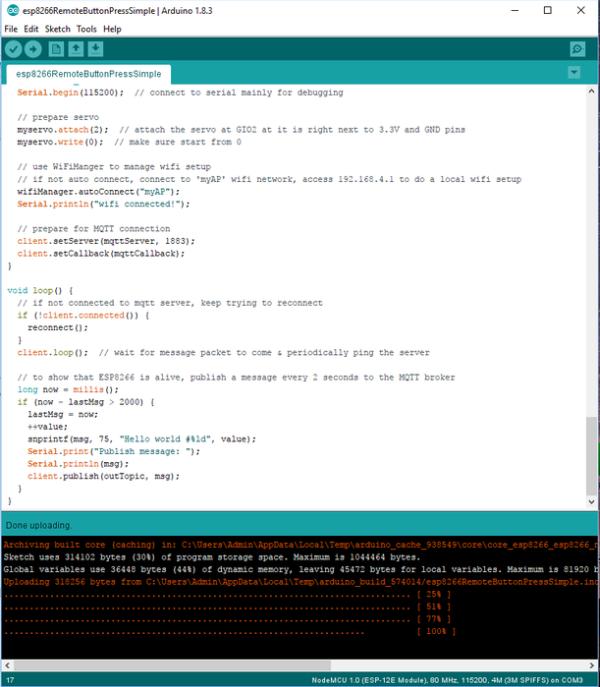
Let’s start a new sketch and insert the following code. Make sure your Arduino IDE environment already installed those 3 libraries above. If not, you should use the Library Manager to install them.
Since this experiment is just a proof of concept, I simplify the code as follows:
- I use a publicly available MQTT broker without worrying about security issues as this is the simplest
- I choose the servo port that just happens to fit the servo cable nicely
- The 2 seconds ping to the MQTT broker is for getting a feedback to make sure the connection is still on. In real application, might need to find a more bandwidth friendly way to do so
- The message payload format which allows modification of angle and duration is meant for fine tuning the actual installation of the servo. Once the servo installation is tested to function properly, these two parameters are not required. Of course, if one need to do a press action that hold for more than a second, like hard reset in computers or the button has different sensitivity, one still can use those parameters accordingly
- The ‘R’ payload message that reset the wifi settings is meant for testing only
/*
 * Remote Button Press
 *
 * This app is using ESP8266 NodeMCU to control a servo which performs an action to press a button.
 *
 * Hardware Requirement:
 * - ESP8266 NodeMCU
 * - 90g servo & connecting wires
 * - power supply
 * - materials help to fix the servo next to the button
 *
 * Software coding is divided into the following parts:
 * - wifi setup
 * - connection to MQTT server and subscribe to a topic
 * - parse incoming message from the MQTT server
 * - activate the servo to perform a press action
 * - feedback to MQTT server when done
 * - Can use <a href="https://eclipse.org/paho/clients/js/utility/" rel="nofollow">https://eclipse.org/paho/clients/js/utility/</a> for testing
 *
 */

#include <ESP8266WiFi.h>
#include <DNSServer.h>
#include <ESP8266WebServer.h>
#include <WiFiManager.h>
#include <PubSubClient.h>  // for MQTT connection
#include <Servo.h>  // for servo movement

const char* mqttServer = "iot.eclipse.org";
const char* inTopic = "esp8266_in";
const char* outTopic = "esp8266_out";
char msg[75];
long lastMsg = 0;
int value = 0;
int duration, posStart, posEnd;
String dString = "";
WiFiClient espClient;
PubSubClient client(espClient);
Servo myservo;
WiFiManager wifiManager;

/*
 * control the servo to mimic a button press action
 * duration in seconds, posStart & posEnd in degrees
 */
void buttonPress(unsigned int duration, unsigned int posStart, unsigned int posEnd) {
  myservo.write(posStart);  // make sure at starting position
  delay(100);  // let servo stops properly

  // start the movement
  myservo.write(posEnd);  // move to ending position
  delay(duration*1000);  // stay there for a given duration
  myservo.write(posStart); // back to starting position
  delay(100);  // let servo stops properly
}

/*
 * handle message arrived from MQTT and do the real actions depending on the command
 * payload format: start with a single character
 * P: button press, optionally follows by (in any order)
 *    Dxxx: for xxx seconds duration,
 *    Exxx: ending at xxx angle
 * R: reset wifi settings
 */
void mqttCallback(char* topic, byte* payload, unsigned int length) {
  // debugging message at serial monitor
  Serial.print("Message arrived [");
  Serial.print(topic);
  Serial.print("] ");
  for (int i = 0; i < length; i++) {
    Serial.print((char)payload[i]);
  }
  Serial.println();

  // parse the payload message
  duration = 1;
  posStart = 0;
  posEnd = 90;
  if ((char)payload[0] == 'R') {
    client.publish(outTopic, "Resetting wifi!");
    Serial.println("Resetting wifi!");  // debug message
    wifiManager.resetSettings();  // reset all wifi settings, should back to AP mode
  } else if ((char)payload[0] == 'P') {
    if (length > 1) {
      for (int i = 1; i < length; i++) {
        dString = "";
        if ((char)payload[i] == 'D') { // modify 'duration', default 1 second
          for (int j = 1; j < 4; j++) {
            dString += (char)payload[i+j];
          }
          duration = dString.toInt();
        }
        if ((char)payload[i] == 'E') {  // modify 'ending position', default at 90 degress
          for (int j = 1; j < 4; j++) {
            dString += (char)payload[i+j];
          }
          posEnd = dString.toInt();
        }
      }
    }
    buttonPress(duration, posStart, posEnd);  // perform servo press
    snprintf(msg, 75, "Button pressed for %d second(s) at %d degrees!", duration, posEnd);
    client.publish(outTopic, msg);
    Serial.println(msg);  // debug message
  } else {
    //snprintf(msg, 75, "Unknown command: %s, do nothing!", (char)payload[0]);
    snprintf(msg, 75, "Unknown command: %c, do nothing!", (char)payload[0]);
    client.publish(outTopic, msg);
    Serial.println(msg);  // debug message
  }
}

/*
 * connect to MQTT with a client ID, subscribe & publish to corresponding topics
 * if failed, reconnect in 5 seconds
 */
void reconnect() {
  // loop until reconnected
  while (!client.connected()) {
    Serial.print("Attempting to make MQTT connection...");
    if (client.connect("ESP8266Client1")) {  // ESP8266CLient1 is a client ID of this ESP8266 for MQTT
      Serial.println("connected");
      client.publish(outTopic, "Hello world, I'm ESP8266Client1");
      client.subscribe(inTopic);
    } else {
      Serial.print("failed, rc=");
      Serial.print(client.state());
      Serial.println(" try again in 5 seconds");
      delay(5000);
    }
  }
}

void setup() {
  pinMode(LED_BUILTIN, OUTPUT);  // just for LED output
  Serial.begin(115200);  // connect to serial mainly for debugging

  // prepare servo
  myservo.attach(2);  // attach the servo at GIO2 at it is right next to 3.3V and GND pins
  myservo.write(0);  // make sure start from 0

  // use WiFiManger to manage wifi setup
  // if not auto connect, connect to 'myAP' wifi network, access 192.168.4.1 to do a local wifi setup
  wifiManager.autoConnect("myAP");
  Serial.println("wifi connected!");

  // prepare for MQTT connection
  client.setServer(mqttServer, 1883);
  client.setCallback(mqttCallback);
}

void loop() {
  // if not connected to mqtt server, keep trying to reconnect
  if (!client.connected()) {
    reconnect();
  }
  client.loop();  // wait for message packet to come & periodically ping the server
		  // to show that ESP8266 is alive, publish a message every 2 seconds to the MQTT broker
  long now = millis();
  if (now - lastMsg > 2000) {
    lastMsg = now;
    ++value;
    snprintf(msg, 75, "Hello world #%ld", value);
    Serial.print("Publish message: ");
    Serial.println(msg);
    client.publish(outTopic, msg);
  }
}
Step 4: Action!
To test the setup, do the followings:
Preparation:
- Connect the servo to the ESP8266 and then power up the ESP8266.
- Remote configure the ESP8266 wifi settings by connecting a computer or handphone to the ‘myAP’ wifi network. Then access the webpage at 192.168.4.1 to setup the wifi connection of the ESP8266. This step is not required unless you reset the wifi network with the ‘R’ MQTT payload command or in a new wifi environment.
- Once the EPS8266 is connect to the wifi network, go to https://eclipse.org/paho/clients/js/utility/ in a browser.
- Connect to the host ‘iot.eclipse.org’, subscribe to ‘esp8266_out‘ topic and keep the QoS at 0. After a few seconds, one should be able to see the ping message from ESP8266 at the bottom of the webpage. If not, verify the ESP8266 wifi settings and make sure it is connected to the Internet and no firewall rule is blocking port 1883.
- Publish a message with a single letter P to the esp8266_in topic. The servo should moves and a message “Button pressed for 1 second(s) at 90 degrees!” near the bottom of the webpage.
- Observe the movement of the servo horn and adjust it according to the required button press action.
Testing:
In this experiment, I simply try to wake a Windows 10 laptop from sleep by pressing the power button.
- Place the servo next to the Windows 10 laptop power button and secure it using double-sided tape.
- Once the ESP8266 is connected to the MQTT broker as seen from the ping message, issue the P message to the esp8266_in topic. If necessary, adjust the duration and the angle using the Dxxx and Exxx parameters in the publish payload, e.g. PD002E120 for a 2 seconds press at 120 degrees. In this particular case, by trial and error, I find that using 75 degrees for 1 second will do. Therefore, I simply publish a PE075 message to the esp8266_in topic to wake the computer from sleep.
Improvement Ideas:
- Either use a custom made MQTT broker or encrypted the payload message to provide an extra layer of security (maybe my next Instructable is to show to setup such a broker in a free Cloud account like Microsoft Azure!) .
- Modify the servo horn or use different types of mechanical linkage to the servo to provide more robust and versatile press action.
- Attach a sensor to verify the button press. For example, if the setup is to control a light switch, a light sensor might be able to give a feedback on the button press action. It is also possible to connect a camera like ArduCAM to ESP8266 to capture images and send over through websocket.
- Create a custom made webpage to connect to the MQTT broker.
- Daisy chain a few similar setup to control a series of buttons that need to be control in sequence using MQTT messaging. For example, power on a power strip before powering up devices attached to the power strip one at a time.
Source: Simple IoT Remote Switch With MQTT and ESP8266
- How does the system connect to the WiFi network?
The project uses the WiFiManager library which automatically connects to a known network or creates an Access Point for configuration if no network is found. - What library is used to handle MQTT connections?
The PubSubClient library is used to connect to an MQTT broker, subscribe to topics, and publish messages. - How can I modify the duration of the button press?
You can modify the duration by adding Dxxx to the payload message, where xxx represents the time in seconds. - Can I change the angle of the servo movement?
Yes, you can change the ending position angle by using Exxx in the payload, where xxx is the angle in degrees. - What command resets the WiFi settings?
Sending a payload starting with the letter R will trigger the reset of the WiFi manager settings. - Which public MQTT broker was used in this example?
The project connects to iot.eclipse.org as a publicly available MQTT broker. - How do I test the setup without a custom app?
You can use the Eclipse Paho web utility at https://eclipse.org/paho/clients/js/utility/ to publish messages to the ESP8266. - What are some suggested improvements for security?
Improvements include using a custom made MQTT broker or encrypting the payload message for better security.