Contents
hide
Summary of Simple Automated Model Railway Layout | Arduino Controlled
Arduino microcontrollers can simplify model railroad automation. This project uses an Arduino, an L293N motor driver, a sensored track, and a 12 V DC supply to automate a simple oval layout. After wiring the motor driver to the Arduino and track, upload the provided sketch, test the loop, and tweak the code for custom behavior.
Parts used in the Simple Automated Model Railway Layout:
- Arduino microcontroller
- L293N motor driver module
- Sensored track
- 12-volt DC power source (at least 1 A / 1000 mA)
- 6 male-to-female jumper wires
- 4 male-to-male jumper wires
- Crosshead screwdriver
- Computer
- USB cable for Arduino
Arduino microcontrollers are a great addition to model railroading, especially when dealing with automation. Here is a simple and easy way to get started with model railroad automation with Arduino.

So, without any further ado, let’s get started!
Step 1: Watch the Video
Step 2: Get All the Stuff
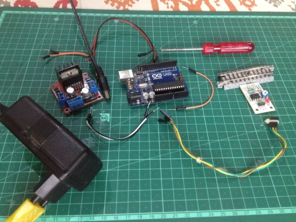
Here is the list of all the parts and components required for this project:
- An Arduino microcontroller
- An L293N motor driver module
- A ‘sensored’ track
- A 12-volt DC power source with a current capacity of at least 1A(1000mA)
- 6 male to female jumper wires (3 to connect the motor driver’s signal inputs to the output pins of the Arduino board and the other 3 to connect the ‘sensored’ track’s terminals to the Arduino board.)
- 4 male to male jumper wires(2 to connect the motor driver board to power and the other two to connect the motor drive’s outputs to track power.)
- A crosshead screwdriver
- A computer(obviously ; )
- A suitable USB cable to connect the Arduino board to the computer
Step 3: Program the Arduino Microcontroller
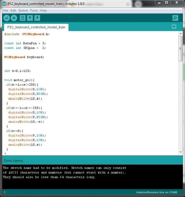
Make sure to go through the program carefully to understand how it works, later it will be fun to tweak it and make your own modifications.
Step 4: Set Up the Layout
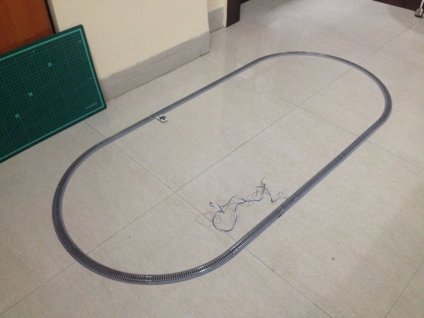
Make an oval loop of track as shown in the picture.
Step 5: Make Wiring Connections to the Motor Driver
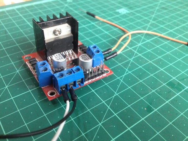
Remove the jumper connector from the pin marked ‘ENB’.
Make the following connections:
- Connect the ‘ENB’ pin to pin D10 of the Arduino board.
- Connect the ‘IN 3’ pin to the pin D8 of the Arduino board.
- Connect the ‘IN 4’ pin to the pin D9 of the Arduino board.
Source: Simple Automated Model Railway Layout | Arduino Controlled
- What core components are required to start this project?
The article lists an Arduino microcontroller, L293N motor driver module, sensored track, 12 V DC power source (≥1 A), jumper wires, screwdriver, computer, and USB cable. - How much current should the power supply provide?
The power source should have a current capacity of at least 1 A (1000 mA). - How many jumper wires are needed and for what?
Six male-to-female jumpers are used (three for motor driver signal inputs to Arduino and three for sensored track terminals to Arduino). Four male-to-male jumpers are used (two for motor driver power and two for motor driver outputs to track power). - Which Arduino pins are used to connect to the L293N motor driver?
Connect ENB to D10, IN3 to D8, and IN4 to D9 on the Arduino. - What must be done before wiring the motor driver connections?
Remove the jumper connector from the pin marked ENB on the L293N module. - What layout should be assembled for this project?
Make an oval loop of track as shown in the article. - Is there code provided and what should be done with it?
Yes, program the Arduino with the provided sketch and review it to understand and later modify behavior. - Where can I watch a demonstration video for this project?
The article links to a YouTube video at https://youtu.be/HqcdEgkYbN8.