Summary of Simple Arduino RGB LED Cube (3x3x3)
I built an affordable, easy-to-assemble 3x3x3 RGB LED cube using WS2812B LEDs and an Arduino Nano, with optional 3D-printed base. The guide covers templates, bending and soldering LED pins for power and data, assembling layers, wiring power and data between layers, trimming pins, and printing/installing a base. Total cost about $20–$50 and build time about a weekend.
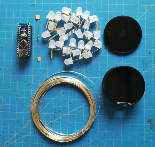
Parts used in the 3x3x3 RGB LED Cube:
- 27 x WS2812B 8mm LEDs
- 1 x Arduino Nano
- 1 x 150 Ohm resistor
- Silver plated copper wire (roll)
- Prototyping PCB board or sheet of plastic (template)
- Glue
- 3D-printed base files (two STL parts) or alternative acrylic/wood case
- Optional: helping hands

I´ve been looking into LED Cubes and noticed that most of them were either to complicated or to expensive. After looking at a lot of different cubes, I finally decided that my LED Cube should be:
- easy and simple to build
- affordable
- very stylish and extravagant
After having build multiple Arduino LED Cubes, I can happily say that I created a really cool looking extraordinary Cube that fits my goals.
Now in this Instructable, I´m going to show you how to build your own RGB LED Cube.
Time required:
about a Weekend
Cost:
20-50$ depending on where you buy from.
Step 1: Equipment and Materials
Tools:
- Soldering Iron
- Cutting Pliers (for cutting the wire)
- Needle Nose Pliers (to bend the LEDs and the wire)
- 3D-printer (OPTIONAL)
- Helping Hands (not necessary but definitely advisable)
Parts:
- 27 x ws2812b LEDs
- 1 x 150 Ohm Resistor
- 1 x Arduino Nano
- a roll of silver plated copper wire
- ~2$ in your local craft store
- Glue
- prototyping pcb board / sheet of plastic
The total cost of this 3x3x3 cube is about 18 $ if you buy everything from Aliexpress.
Software:
- Arduino IDE (free)
- CUDA (or your own Slicer for your 3D Printer)
Step 2: Preparing to Solder
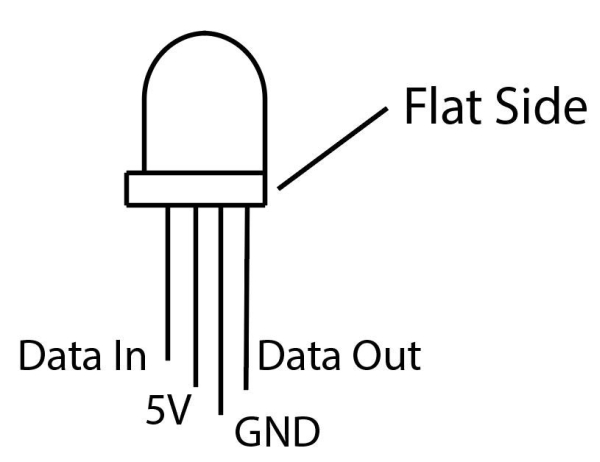
First we have to create a template, so it’ll be easier to solder the LEDs together. I used a prototyping pcb board for this and marked two holes for the middle pins of the LED, which are for power supply (as seen on the graphic).
When I built a 5x5x5 version of this cube, I used a sheet of plastic for the template, which also worked very well. If you use plastic or wood, you should drill the pair of holes about 2,4 cm (or 0,95 inches) apart.
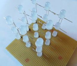
Step 3: Bending and Placing the LEDs
Parts required for this step:
- 27 ws2812b 8mm LEDs
- silver plated copper wire
- prototyping pcb board
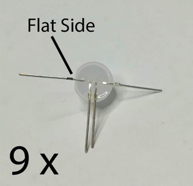
In this step you have to bend the pins of 18 LEDs as shown in the picture above. The remaining 9 LEDs have to be bend so that the “Flat Side” will be facing the other direction. After that 9 LEDs with the flat side on the same side must be placed on the breadboard / sheet of plastic.
Additionally, 18 pieces of wire have to be cut. They have to be about 2 cm longer than your LEDs are high. For me, this turned out to be about 6cm (or 2,4 inches).
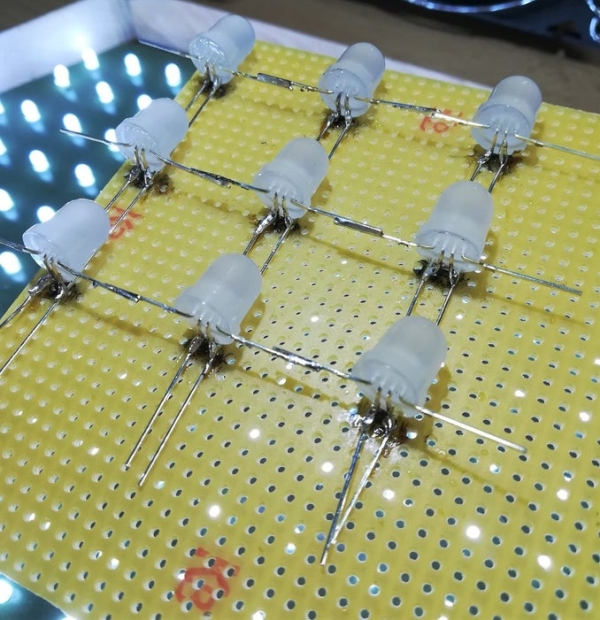
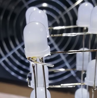
Step 4: Soldering the Power
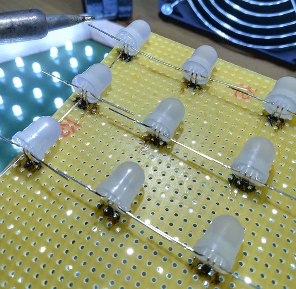
Now you solder the tip of the piece of wire to the top LED as shown in the first picture. Then you solder the wire to the LEDs below. Make sure that no wires are touching each other, or else there’ll be a short-circuit; then solder the other wires to the LEDs.
Step 5: Soldering the Data Pins
This should be easy. You just have to align the data pins from the LEDs and solder them together as shown in the picture.
Step 6: Removing the LEDs and Cutting the LED Pins
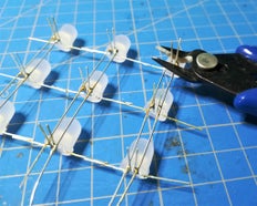
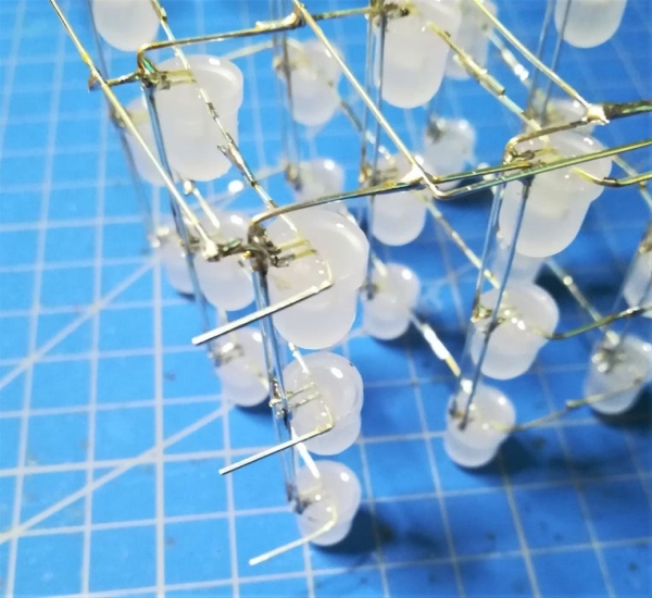
You can remove the LEDs from the template by simply pushing them onto a flat surface as shown in picture one.
After removing the LEDs, you have to cut the remaining ends of the LED pins. After that it should look like in picture 3 and 4.
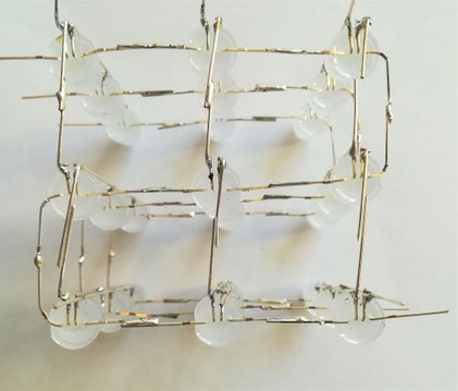
Step 7: Soldering the Data Lines of the Layers Together
First you have to place the previously soldered vertical layers in form. While making sure that the distance between the rows is equal, you solder the data pins together as shown in the pictures.
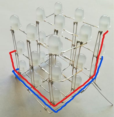
Step 8: Connecting the Power Wires
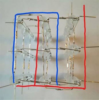
Now you bend the ends of the silver plated copper wire as shown in the pictures. It is very important to cross the wires so that GND is connected to GND, and 5V to 5V.
The wires on the outer layers should be bend outwards.
After you have bend all of the wires you go on to soldering them together.
Step 9: Connecting the Power Wires Part: II
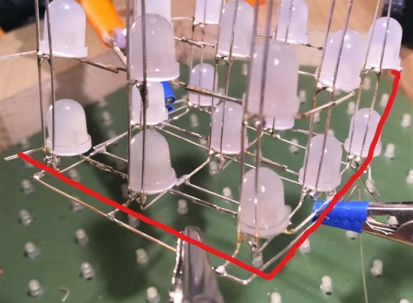
Now it is time to connect the previously soldered power pins. To accomplish this you bend two pieces of wire as shown in the pictures.
Note: Make sure that you have plenty of wire left at the left corner, because this is what we will use to connect to our base.
After having bend the wire into the right shape, you solder them to the pins.
Then solder an additional piece to one of the power wires (the red one in the picture)
Finally, you cut of the rest of the pins as shown in the last picture.
Step 10: Data Wiring Part I: Bending the LED Pins
In this step you just have to bend all the remaining data pins as shown in the picture.
Step 11: Data Wiring Part II: Connecting the First to the Second Layer
After you have bend the pins of the ws2812b Leds, you are now going to connect the Data OUT from the first layer to the Data IN of the second one.
To accomplish that you have to bend a piece of wire in to the shape shown in picture 2, which will be used to connect the layers as drawn in the first picture.
The next step is to solder one end of the wire to the Data OUT pin of the first layer. The Data OUT pin is the pin on the flat side of the LED.
The other end is then soldered to the Data IN of the second layer, which is one of the previously bend LED pins on the round side of the LED.
Step 12: Data Wiring Part III: Connecting the Second to the Third Layer
Next you connect the second to the third layer.
Just like in the step before, you now bend a piece of wire in shape as shown in picture 2. The wire should be bend in this way so it will not obstruct the light of the LEDs and to guarantee an elegant look of the cube.
You then start to solder the short end of the wire to the Data OUT pin of the second layer and the other end to the Data IN LED pin (the one on the round side) .
After having done that, you cut the remaining end of the wire.
Step 13: Data Wiring Part IV: Soldering the Last LED
To finish the data wiring you now have to bend the Data OUT pin on the flat side of the top layer LED (as shown in the first picture) so that it touches the ground pin.
You then go on to soldering the the pins together and cutting the remaining end off.
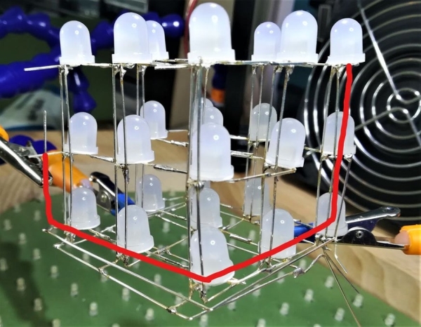
Step 14: Data Wiring V: Completed Result
Now you have finished the building of the LED cube itself. Here are some reference pictures if you had problems understanding the steps before.
Step 15: 3D-Printing the Base
For this Instructable I have designed a simple, but elegant base, which also serves as the case of the Arduino nano, but if you like, I would appreciate if you share your ideas/ files for another casing. Anyway, you now need access to a 3D-printer. If you don’t have one at home, you could go to your local maker space. I have linked the files for you below so you just have to do the following:
- Download the two .stl files from below
- Import them into the slicing software you or your maker space use
- Slice them using the settings below
- Convert to gcode
- Start printing
Slicer settings:
- Layer height: 0.1 mm
- Infill >20%
- Wall line count > 2
- High quality print speed settings (depends on your printer)
You only need to print each part once! After starting a print I suggest to relax, or carry on with the other steps, as the prints take about 2-3 hours combined.
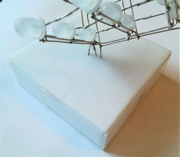
If you don’t own or have access to a 3D printer I suggest that you build a simple case, using acrylic or wood for example, as in the picture above.
Source: Simple Arduino RGB LED Cube (3x3x3)
- What is the estimated cost to build the 3x3x3 RGB LED Cube?
About 20–50$ depending on where you buy parts; about 18$ if bought from Aliexpress. - How long does it take to build the 3x3x3 RGB LED Cube?
About a weekend. - Which LEDs are used in this cube?
WS2812B 8mm LEDs, 27 pieces for the 3x3x3 cube. - What microcontroller is used to drive the cube?
An Arduino Nano is used. - Do I need a 3D printer for the base?
A 3D printer is optional; you can use acrylic or wood to build a case if you don't have access to a printer. - What tools are required to assemble the cube?
Soldering iron, cutting pliers, needle nose pliers, and optionally helping hands and a 3D printer. - How are the LEDs arranged and connected?
LEDs are formed into three vertical layers; power pins are soldered in columns and data pins are chained from layer to layer (Data OUT to next layer Data IN). - What template can be used to position LEDs for soldering?
A prototyping PCB board or a sheet of plastic or wood with holes about 2.4 cm apart is used as the template. - Is specific software required for the project?
Arduino IDE is required for coding; a slicer such as Cura is used for printing the base STL files.