Summary of A Simple Arduino LCD Min/Max Thermometer
This article details a beginner Arduino project creating a Min/Max thermometer using an LM35DZ temperature sensor and a Displaytech 162B LCD. The setup involves reading analog voltage from the sensor, converting it to Celsius, and displaying the data on the screen in 4-bit mode to conserve digital I/O pins. A potentiometer is used for contrast adjustment, and a resistor protects the backlight LED.
Parts used in the Arduino Min/Max Thermometer:
- Arduino board
- Displaytech 162B LCD (HD44780 compatible)
- LM35DZ temperature sensor
- Breadboard
- 50K potentiometer
- Small resistor for backlight
- LCD4Bit library
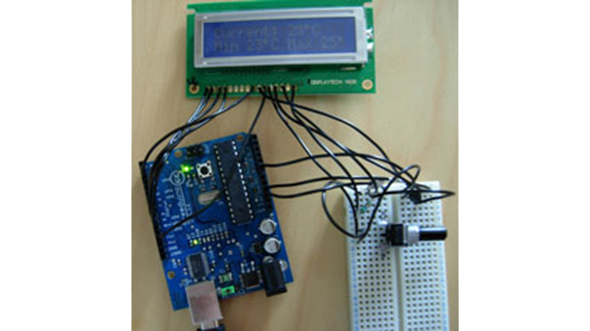
As a simple first Arduino experiment I interfaced a two line LCD (a Displaytech 162B) and an LM35DZ to make a simple Min/Max thermometer.
Step 1 – Interfacing the Temperature Sensor
This is really very simple. The LM35DZ has three pins, +5V, ground and a variable voltage output to indicate the temperature. I plugged it into breadboard and wired the output straight to the Arduino’s analogue input 0.
To test we can run a program to read the sensor, do the conversion to degrees celcius and then output it to the serial port (since we don’t have an LCD quite yet).
int potPin = 0;            // select the input pin for the LM35
float temperature = 0;

void setup()
{
  Serial.begin(115200);
}

void loop()
{
  if (Serial.available())
  {
    val = analogRead(potPin);    // read the value from the sensor
    temperature = (5.0 * val * 100.0)/1024.0;
    Serial.println((long)temperature);
  }
  delay(1000);
}
Remember to use the arduino IDE’s serial monitor to look for the output when run – it won’t appear unless you select it!
Step 2 – The LCD module
The Displaytech 162B is a HD44780 compatible device, and it’s easy to find guides on how to interface them with the Arduino. They can be driven with a eight data lines – which uses up most of the digital I/O pins on the Arduino, or more sensibly you can use 4 bit mode.
I started with 8 bit mode, and whilst it worked it’s so trivial to use 4 bit instead it’s not worth the extra wires! I also couldn’t get both lines of the display working in 8 bit mode.
I connected the LCD like so – remember yours may differ :
LCD Pin                    Connected to
1  Backlight Anode         +5V (via small resistor)
2  Backlight Cathode       GND
3  Ground                  GND
4  Supply V for Logic      +5V
5  Input Voltage for LCD   Middle pin of 50K potentiometer
6  RS (Data/Instruction)   Ard pin 12
7  R/W (Read/Write)        GND
8  E (Enable)              Ard pin 2
9  Data bit 0
10 Data bit 1
11 Data bit 2
12 Data bit 3
13 Data bit 4              Ard pin 7
14 Data bit 5              Ard pin 8
15 Data bit 6              Ard pin 9
16 Data bit 7              Ard pin 10
The other two pins of the potentiometer are connected to +5V and GND and provide a contrast control (and you will need it at least initally). 50K is over the top for the purpose, 10K is more typical, but it isn’t an issue.
The resistor on the backlight was added because the backlight LED on the board was getting rather warm. The display stays bright enough and runs a bit cooler with a resistor on the supply.
The pin allocations on the Arduino were dictated by the LCD4Bit library, but you could easily change them in the library if you needed to.
You can take the test code and library straight from the Arduino Playground 4-bit LCD page.
Run it and verify your LCD is printing “arduino” as the program runs – you will probably need to twist the potentiometer to get a readable display.
Read More: A Simple Arduino LCD Min/Max Thermometer
-
How do you connect the LM35DZ sensor?
Connect the +5V pin to power, ground to GND, and the variable voltage output directly to the Arduino's analogue input 0. -
What formula converts the sensor value to degrees Celsius?
The code uses the formula: (5.0 * val * 100.0)/1024.0 to calculate the temperature from the analog read value. -
Why is 4-bit mode preferred over 8-bit mode for the LCD?
4-bit mode is preferred because it uses fewer digital I/O pins on the Arduino and avoids issues where only one line of the display works in 8-bit mode. -
Which Arduino pins are used for the LCD control signals?
In this setup, RS connects to pin 12, Enable to pin 2, and data bits 4 through 7 connect to pins 7, 8, 9, and 10 respectively. -
What is the purpose of the potentiometer connected to the LCD?
The potentiometer provides contrast control by connecting its middle pin to the Input Voltage pin of the LCD module. -
Why was a resistor added to the LCD backlight circuit?
A resistor was added to the Backlight Anode to prevent the LED from getting too warm while maintaining sufficient brightness. -
How can you verify the LCD is working correctly?
Run the test code to see if it prints "arduino" on the display, adjusting the potentiometer until the text is readable.