Summary of Sensor Stations Network for Lighting and Security Control
This article details a home automation system using a master/slave sensor network for lighting and security. The setup includes slave nodes (Node01, Node02) with PIR sensors and a master node (Node00) connected to Wi-Fi. Key features include remote mobile control, email alerts upon motion detection during alarm mode, automatic light switching, and audible alarms triggered by motion across the network.
Parts used in the Sensor Stations Network:
- Mega 2560 R3 board
- Plastic support for MEGA 2560 R3
- HC-SR501 PIR sensor
- Plastic support for HC-SR501
- 5V Relay
- Wireless Transceiver Module 2.4G 1100m NRF24L01+PA+LNA with Antenna LKY678
- Pin NRF24L01 adapter
- HLK-PM01 AC DC 220V to 5V Mini Power Supply
- WiFi module NodeMCU Lua Amica V2 ESP8266
- 5v-3.3v VCC adapter board for NRF24L01
- Adapter AC-DC, 9V, 1A
- Pin 5 mm PCB connectors
- Jumper wires
- Breadboard MB-102
- Mini Solderless Breadboard 170 contacts
- Set of leds and resistences
- PCB boards
- Tin Soldering Iron Kit
- Glue gun
- Transparent methacrylate
- Bell
With this sensor stations network configured in a master/slave mode, you will be able to do lighting and security control in your home. These sensor stations (Node01, Node02 in this project) are connected to a master station (Node00) connected to your local wifi network. I have installed the Node01 in my storage room and the Node02 in my garage controlling lights and motions. The master station is installed in our dinig room connected to our wifi router. I have installed the bell in the garage and a little buzzer in the master station to sound when a motion is detected by some sensor station in the network.
The main features of the network are:
- It is possible to configure a network with more than two sensor stations (slave stations) (Node01, Node02, Node03, ….)
- Because the use of wireless transceivers with antenna, the network is able to cover a wide area
- You can control the whole network from a mobile phone
- Send a email (Gmail account) when a motion is detected and the alarm mode is enable. So if you enable the Gmail push notifications in your mobile you will know when a movement is detected in your network
for domotic purposes:
- Switch on the lights when a motiont is detected / switch always on the lights (for the whole network or for each slave station)
- Change the time in minutes the lights is on after a motion has been detected for each slave station
for security purposes:
- Enable and disable the alarm mode
- Each slave station is able to send a signal to a master station (Node00) when the alarm mode is enable and a motion is detected
- The master station is able to activate a bell and send a email when one of these signal is received from any slave station and the alarm mode is enable. The master station (Node00) is connected to internet using a wifi connection to control the whole system using a mobile phone. It is configured like a WifiWebServer
Step 1: List of Material
The list of material I have used to build Node01 and Node02 (slave stations) is the following:
- Mega 2560 R3 board
- Plastic support for MEGA 2560 R3
- HC-SR501 PIR sensor
- Plastic support for HC-SR501
- 5V Relay
- Wireless Transceiver Module 2.4G 1100m NRF24L01+PA+LNA with Antenna LKY67
- 8Pin NRF24L01 adapter (to improve the features of the NRF24L01)
- HLK-PM01 AC DC 220V to 5V Mini Power Supply
The list of material to build the Node00 (master stations) is the following:
- Mega 2560 R3 board
- Plastic support for MEGA 2560 R3
- WiFi module NodeMCU Lua Amica V2 ESP8266
- Wireless Transceiver Module 2.4G 1100m NRF24L01+PA+LNA with Antenna LKY67
- 5v-3.3v VCC adapter board for NRF24L01 (to improve the features of the NRF24L01)
- Adapter AC-DC, 9V, 1A (2,1 mm x 5,5mm)
Moreover I have used the following material:
- 2 Pin 5 mm PCB conectors
- Jumper wires
- Breadboard MB-102 (800 contacts)
- Mini Solderless Breadboard 170 contacts
- Set of leds and resistences
- PCB boards
- Tin Soldering Iron Kit
- Glue gun
- Transparent methacrylate
- Bell
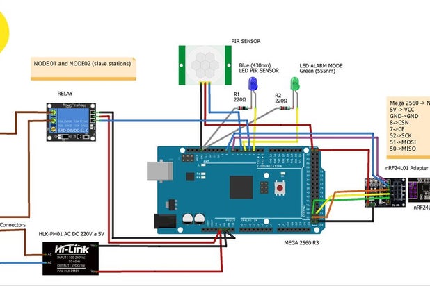
Step 2: How to Connect and Program Node01 and Node02 (Slave Stations)
To program the sketch “SlaveSation.ino” I heve needed the RF24 library and the RF24 Network library.
In the flow chart above you can see the logic of the sensor station and the messages exchanged between a slave sensor station and the master one.
Before you load the sketch you have to configure the address of the slave node in octal format
const uint16_t this_node = 01; // Address of our node in octal format (slave): 01, 02, 03 ...
The meaning of the leds in each slave stations is the following:
- Blue led. It will be on while the PIR sensor pin is high.
- Green led. It will be on when the alarm is connected.
Step 3: How to Connect and Program Node00 (Master Station)
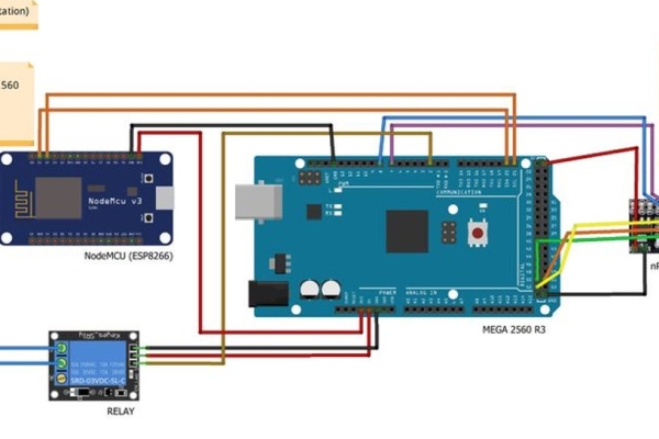
In the Node00 station we can find two different boards:
- MEGA 2560 R3 board. This device is used to receive messages from slaves station when a motion is detected using wireless communicaction. It will activate a bell when a movement is detected and the alarm is connected. To stop the bell just only disconnect the alarm mode. Moreover it sends to the slaves station messages from NodeMCU to enable or disable motion detection, to turn always on the lights, to turn always off the lights, …
- NodeMCU Lua Amica V2 ESP8266 board. It works like a Wifi Web Server to transmit and receive commands from a remote place using a Web page in a mobile phone. Moreover sends e-mail messages when a motion is detected and the alarm mode is enabled.
Both devices are programmed to communicate with one another in a Master(NodeMCU)/Slave(MEGA) configuration via the I2C synchronous serial protocol using the Wire Library. The I2C protocol involves using two lines to send and receive data: a serial clock pin (SCL) and a serial data pin (SDA) over which data is sent between the two devices.
As you can see in drawing, the two pins for the I2C communication in the MEGA 2560 R3 board are:
- SDA -> pin 20 SDA
- SCL -> pin 21 SCL
and the other ones in the NodemMCU are:
- SDA -> digital pin 1
- SCL -> digital pin 2
Before you load the sketch for the ESP8266 you have to install the ESP8266 board. To do that you have to enter “http://arduino.esp8266.com/stable/package_esp8266com_index.json” into the “Additional Board Manager URLs” in the preferences window in the Arduino IDE. After that you have to open boards manager and install “esp8266”
I use a external power supply adapter (9V , 1A) for the MEGA 2560 R3 board (DC power jack, 2,1mm x 5,5 mm) and I connect the NodeMCU board to the 3V3 pin in the MEGA board.
Source: Sensor Stations Network for Lighting and Security Control
- How many sensor stations can be configured?
The network supports more than two sensor stations, allowing for multiple slave nodes like Node01, Node02, Node03, etc. - Can I control the whole network from a mobile phone?
Yes, you can control the entire network remotely via a mobile phone using the WifiWebServer configuration. - Does the system send emails when motion is detected?
Yes, it sends an email via a Gmail account if the alarm mode is enabled and motion is detected. - What happens when a motion is detected while the alarm is on?
The master station activates a bell and sends an email notification to the user. - How are the lights controlled based on motion?
Lights can be switched on automatically when motion is detected or kept always on for specific periods per slave station. - Which wireless module is used for communication between nodes?
The project uses the Wireless Transceiver Module 2.4G 1100m NRF24L01+PA+LNA with Antenna LKY678. - How do the NodeMCU and Mega boards communicate?
They communicate via the I2C synchronous serial protocol using the Wire Library over SDA and SCL pins. - What libraries are needed to program the slave stations?
You need the RF24 library and the RF24 Network library to program the SlaveStation.ino sketch.