Summary of RS485 – ARDUINO AND INDUSTRIAL DISTANCE SENSOR
This article details a project connecting an industrial RS485 distance laser sensor to an Arduino for real-time distance measurement. The author successfully configured the communication protocol and displayed readings on a custom LoL Shield Matrix screen, demonstrating a cost-effective solution for industrial object detection using accessible hardware.
Parts used in the Distance Laser Sensor Project:
- Arduino Uno R3
- Arduino Mega 2560
- Module RS-485
- LoL Shield Matrix
- Distance Laser Sensor
- 40 pin male header (4 pcs)
- 40 pin female header (4 pcs)
- Double Side Prototype PCB
- Ribbon Cable
- Power Supply 5VDC and 24VDC
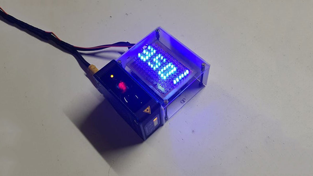
I have in my hand a distance laser sensor with high precision and speed. It is used in industrial environments for object positioning or detection applications. According to technical documents, I found it can communicate with other devices via RS485. I spent the weekend to learn it and find ways to communicate with cheap CPU – Arduino. And finally, I succeeded in reading data from it and displaying the distance value on the led screen.
And I’m willing to share this test with you. Let’s start with the video below:
Step 1: B.O.M
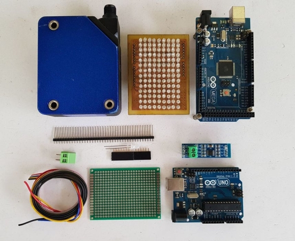
Main components include:
- Arduino Uno R3.
- Arduino Mega 2560. (Option to check the RS485 communication because it has multiple serial ports. We can use Arduino Mega 2560 to print the value on Arduino IDE for program debugging).
- Module RS-485. It is very cheap, about $0.4 on AliExpress.
- LOL Shield Matrix. For LoLShiled, I did it by myself at home. You can refer to PCB design at: https://github.com/jprodgers/LoLshield & make one for yourself.
- Distance Laser Sensor.
- 40 pin male header (4 pcs).
- 40 pin female header (4 pcs).
- Double Side Prototype PCB.
- Ribbon Cable.
- Power Supply 5VDC and 24VDC. For me, I used a power supply PS 307 from Siemens.
Step 2: CIRCUIT DIAGRAM AND ASSEMBLY
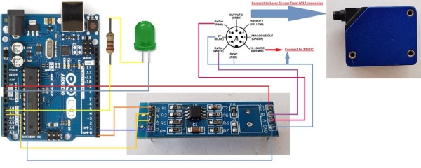
The circuit schematic is shown on picture above.
My idea is to read distance data and display this value on LoLShield. To do this, I had to turn the RS-485 module into a Shield to plug it on the Arduino and then Lolshield matrix will be plugged on the top.
- Soldering RS-485 Shield:
RS-485 Shield after soldering with male header at bottom and female header on the top.
Read more: RS485 – ARDUINO AND INDUSTRIAL DISTANCE SENSOR
- How can I communicate with a cheap CPU like Arduino?
You can use an RS485 module to enable the Arduino to read data from the sensor. - What is the best way to debug the program?
Use an Arduino Mega 2560 because it has multiple serial ports to print values in the Arduino IDE. - Can I build my own LoL Shield Matrix?
Yes, you can refer to the provided GitHub link to design and make one yourself. - How do I connect the RS-485 module to the Arduino?
Solder male headers at the bottom and female headers on top to turn the module into a shield. - What power supplies are required for this setup?
The project requires both 5VDC and 24VDC power supplies. - Does the sensor support industrial environments?
Yes, the distance laser sensor is designed for industrial environments for object positioning or detection. - Where can I find the PCB design for the LoL Shield?
The design is available at the GitHub repository linked in the article. - What is the approximate cost of the RS-485 module?
The module costs about $0.4 on AliExpress.