Today I will share how to make a WIFI JOYSTICK from an ESP8266 and 4 ways industrial joystick. It can be integrated into the factory’s automation system or be used for smart home control. The mentioned control systems are PLCs and the specific case that I am applying is SIEMENS PLC S7-300….. Let’s start and firstly please watch the video below:
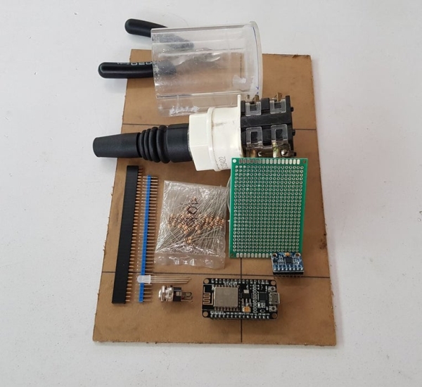
Step 1: BILL OF MATERIAL

Main components for Wifi Joystick:
- 1pcs x NodeMCU ESP8266 V1.0.
- 1pcs x Industrial 4 ways Joystick.
- 1pcs x NeoPixel Ring 16.
- 1pcs x MPU-6050 (Optional).
- 1pcs x RGB LED (Optional).
- 1pcs x Single/Double Sided Printed Prototyping Board.
- 1pcs x Male and Female 40pin 2.54mm Header Socket Row Strip PCB Connector.
- 1pcs x XH2.54mm – 2P 20cm Wire Cable Double Connector.
- 1pcs x XH2.54mm – 4P 20cm Wire Cable Double Connector.
- 1pcs x XH2.54mm – 5P 20cm Wire Cable Double Connector.
- 4pcs x R10K.
- 1pcs x Power Supply Adapter 5V/2A.
- 1pcs x DC Power Jack supply socket.
- Acrylic Tube. I used a cylindrical tube with outer diameter 65mm, thickness 3mm and length 75mm.
- Some wires.
For material parts of PLC system, you can refer to my instructable: https://www.instructables.com/id/ARDUINO-HACK-PLC… Main components are include:
- POWER SUPPLY PS307 5A.
- SIEMENS PLC CPU 314C-2DP.
- SIEMENS CP 343-1 LEAN.
- 4pcs x Relay 24VDC and relay base.
Step 2: SCHEMATIC AND CIRCUIT ASSEMBLY
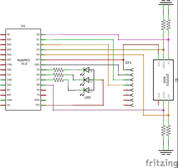
Firstly, I assembled the circuit following below diagram. It includes MPU-6050 and one RGB LED to display the joystick status.

It looks like that for 1st version:
Read more: WIFI JOYSTICK
