This instructables show how to use a square color display and Arduino dev board build a watch core.
This will cover the topics of dev board selection, display selection, extra modules selection, UI design, performance tuning and power saving.
Note:
I have prototyped some Arduino Watches few years ago. But the hardware sizes at that time are too big to squeeze into a watch case, so the project have suspended at that time.
Step 1: Power Consumption Concern
A watch have limited space to fit a battery, it should be below 200 mAh or even below 100 mAh.
On the other hand, a watch require a long enough battery life. A normal quartz watch can last at least 1 year, a device with color display nearly not possible to last this long period. As a watch, it should at least can last a day and preferred last over a week.
If 100 mAh battery would like to run a week:
100 mAh / 7 days / 24 hours ~= 0.6 mA
So the current usage while standby should not over 0.6 mA.
Step 2: Dev Board Selection
There are tons of dev boards supported by Arduino IDE. Most of them have a USB to Serial chip for communicating with the computer. It is very helpful for development but most of them failed to cut the power consumption while powered by battery. The chip draws few mA continuously, it cannot meet the standby power consumption requirement.
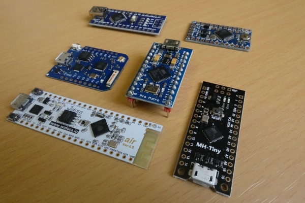
The simplest way to avoid this power consumption is select a board that do not have built-in USB to Serial chip. There are 2 Arduino dev board available:
- Arduino Pro Mini, it has a FTDI pin header for connecting to an external USB to Serial adaptor, after upload the program you can detach the cable to save the power. It consume below 0.04 mA in deep sleep mode if removed power LED.
- Sparkfun Pro Micro, the on board MCU ATmega32U4 also can act as an USB transceiver itself. So you can direct communicate with computer without extra adaptor. It consume around 0.1 mA in deep sleep mode if removed power LED.
The above 2 dev boards both have 3.3 V @8MHz version, so it can direct power with Lipo battery without extra step up circuit.
I like Pro Micro not require extra adaptor while uploading new program, so I will choose Pro Micro in this project.
Ref.:
https://store.arduino.cc/usa/arduino-pro-mini
https://www.sparkfun.com/products/12587
https://www.iot-experiments.com/arduino-pro-mini-p…
Step 3: Display Selection
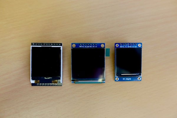
I have decided to use an analog watch face, so it is better to use a square display. I can find 3 type of square display in the hobbyist market:
- ST7735 LCD, resolution is 128 x 128. This is a typical square display in Arduino world. It has various versions come from various manufacturers and many display library support this. But the viewing angle is very limited.
- SSD1351 OLED, resolution is 128 x 128. OLED have much better viewing angle and also can save much power if the screen layout mainly in black (pixel not turn on). But it require extra step up circuit to 15 V for powering the OLED, so it become very thick in size.
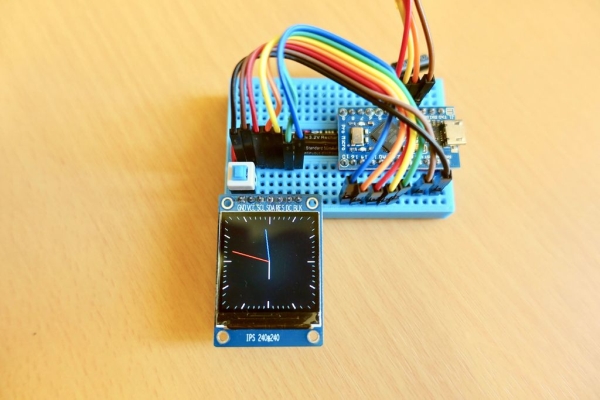
- ST7789 IPS LCD, resolution is 240 x 240. IPS LCD have very good viewing angle, higher resolution and very thin in size.
ST7789 IPS LCD appear in the market since around 2018, it should be tailor-made for smart watch market. I think it is a much better option for building an Arduino watch.
Step 4: Time Sync
There are few way the watch can sync the correct time:
- Compile time stamp, it is the simplest way to sync the time without extra hardware. While compile time, it can embed the current computer time in the code, so Arduino can direct use that time add millis() to get the current time. But it have many limitation, e.g. the time will be wrong after reset, the MCU internal timer is not so accurate, it can drift few seconds a day, … etc.
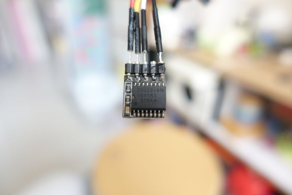
- Real Time Clock (RTC) chip, it is an individual chip dedicate to count the time. Some chip e.g. DS3231 built-in crystal oscillator, so no extra electronics component required. It only consume 0.1-0.2 mA continuously.
- GPS module, GPS signal encapsulated current timestamp for calculating location. So you always can get the correct time once you go outdoor. It consume around 20-40 mA while receiving GPS signal but it enter sleep mode while not in use.
- WiFi + NTP, computer and smartphone both sync the time with the NTP server on the internet. Arduino watch also can use a WiFi module to connect to an AP and sync the time with NTP server. It require 70-150 mA while connecting WiFi, it also can enter sleep mode while not in use.
Among the above options, RTC chip is the smallest, cheapest, less power consumption and reliable solution, so I will use this way in Arduino Watch Core.
Read more: Arduino Watch Core