
Summary of RS232 to RS485 Module
This article describes a project for an RS232 to RS485 interface module designed to connect computers to RS485 networks. The circuit utilizes MAX232 and MAX485 ICs, featuring a 9-pin female D-connector, specific jumpers for power configuration, LEDs for status indication, and diodes for polarity protection. It supports both receiver and transmitter modes via pin control and includes impedance matching components for cable connectivity.
Parts used in the RS232 to RS485 Interface Module:
- MAX232 interface IC
- MAX485 interface IC
- 9 pin female "D" connector
- Connector J1
- Connector J2
- Connector CN1
- Connector CN2
- Jumper J4
- LED D2
- Diode D1
- Power Supply section (optional)
- Resistors R3, R1, and R4
C020
This project is a RS232 to RS485 interface module
Description
This project provides a simple and easy solution to connect your computer to a RS485 Network in either Receiver or Transmitter mode.
This circuit has been designed around popular MAX232 and MAX485 interface IC.
An Onboard 9 pin female D connects this PCB to the Serial Port cable (not supplied with the Kit). Connector J1 and J2 provide the MAX232 IC input/output (IO) and Connector CN1 provide MAX485 IO. An optional Power Supply section can provide regulated 5V DC to the circuit and can be included to power by bridging Jumper J4. LED D2 provides visual indication of power on this board and Diode D1 prevents against reverse polarity connection of power supply at J3. This circuit can also work on 5V supply from the host interface which can be provide through J1 in which case you need to remove Jumper Link @ J4. Connector J2 provide extra connection of the other set of level shifter with in the MAX232 IC.
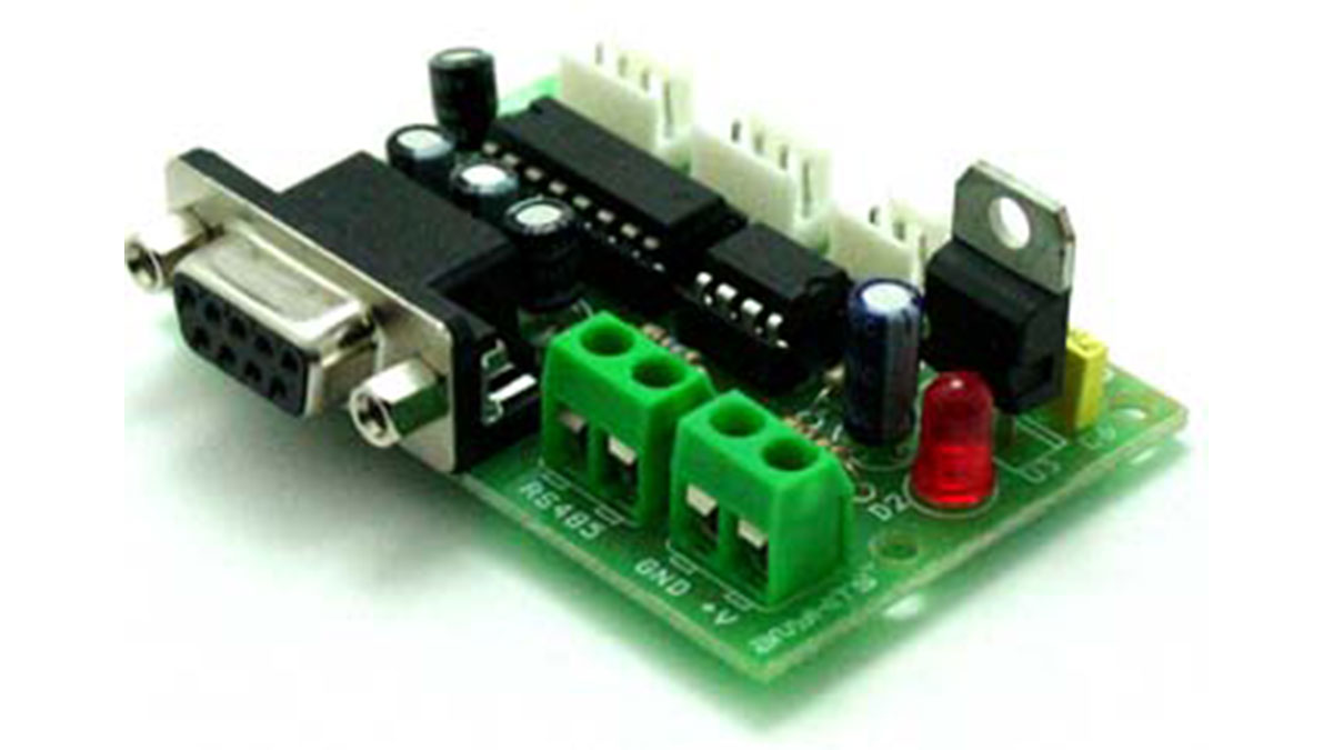
RS485 cable is to be connected at Connector CN2 and are impedance matched with Components R3, R1 and R4.
Terminal marked A on CN1 is the Receive / Transmit control Pin for the RS485 flow control. Pulling this pin to Gnd will enable the Receiver on the RS485 and Pulling it High (connecting it to Vcc) will enable it to work in the transmit mode.
To connect the MAX232 IC to the MAX485:
Connect Pin marked C on connector J1 to Pin marked DI on connector CN1
Connect Pin marked B on connector J1 to Pin marked RO on connector CN1
Connector J1 connects to the Host for power supply and serial In/Out signals.
A Provides data from the Computer to the Host (RXD)
B Provides data to be sent to the Computer from the Host (TXD)
For More Details: RS232 to RS485 Module
-
What is the primary function of this project?
This project provides a simple solution to connect a computer to a RS485 Network in either Receiver or Transmitter mode. -
Which ICs are used to design this circuit?
The circuit has been designed around popular MAX232 and MAX485 interface ICs. -
How do you enable the Receiver on the RS485?
By pulling the Terminal marked A on CN1 to Gnd. -
How do you enable the Transmitter mode?
You must pull the Terminal marked A on CN1 High by connecting it to Vcc. -
Can the circuit work without the optional Power Supply section?
Yes, the circuit can work on a 5V supply from the host interface provided through J1 if you remove the Jumper Link at J4. -
What is the purpose of Diode D1?
Diode D1 prevents against reverse polarity connection of the power supply at J3. -
Where should the RS485 cable be connected?
The RS485 cable is to be connected at Connector CN2. -
Which pins connect the MAX232 IC to the MAX485?
Pin C on J1 connects to Pin DI on CN1, and Pin B on J1 connects to Pin RO on CN1.
