Summary of Romantic Led Heart SMD
This project details a portable, custom-designed LED heart powered by two CR2032 batteries. The creator used the Attiny85 microcontroller and 74HC595 shift registers to drive red LEDs on a double-sided PCB, aiming for a small form factor without an enclosure. The build emphasizes minimal tools, utilizing SMD components and a toner transfer method for PCB fabrication.
Parts used in the Romantic Led Heart SMD:
- 14x 100ohm Resistors (0805 package)
- 14x Red LEDs (PLCC2 package)
- 1x 10k Resistor (0805)
- 1x LM7805 voltage regulator (TO252 package)
- 1x 0.33uF SMD capacitor
- 1x 0.1uF SMD capacitor
- 2x 74HC595 (DIP package)
- 1x Attiny85 (DIP package)
- 1x Tactile switch (through hole)
- 2x CR2032 battery holder
- 2x CR2032 battery
- 1x Slide switch
- 1x Two sided copper clad board
Hi makers!
This is my first instructables and I want to address some important things firts:
- I made this project with the idea of using the lest amount of tools so that everyone could do it! Even I don’t have lot’s of tools, only the strict necessary
- I’m not an electrical engineer or a coder, all that I know I’ve learned on instructables or other sites! The little I know od coding is from a class on C that I’ve attended in university during my physics degree.
- Last but not least, english isn’t my first lenguage so I’m sorry if i make any mistake, in case let me know!
I started thinking about a LED heart after seeing the instructables by the user LexanPanda Animated LED Heart, my project is highly inspired by his, the main difference in mine is the PCB layout: I wanted a small form factor that looked cool even without an enclosure! My version is powered by two CR2032 batteries to make it even more portable.
All the credits for the Arduino program goes to LexanPanda apart for some animations of my own!
I apologize for the lack of photos but from the start I didn’t think that I would make an instructables, but changed my mind at the last minute!
Now as you can see, if I have done it, everybody can! I hope you like it, let’s jump right into it.
Step 1: Parts
Here is the list of parts that I’ve used, there are a lot of SMDs but, if I haven’t convinced you before, I’m not an expert by any means. Everyone can solder SMDs with a little bit of patience, tweezers and a small enough soldering iron tip.
Parts list:
- 14x 100ohm Resistors (0805 package)
- 14x Red LEDs (PLCC2 package), you can use every color you want, be sure to choose the right resistor for the color tho. Here is a site that can help you with that (Supply: 5V, for led voltage drop and current see this site, number of LEDs: 1)
- 10k Resistor (0805) this is for the pull down
- LM7805 voltage regulator (TO252 package)
- 1x 0.33uF SMD capacitor (I’ve used Tantalum caps, but that’s optional, I only had those in my drawers)
- 1x 0.1uF SM capacitor (Same Tantalum)
- 2x 74HC595 (DIP package)
- 1x Attiny85 (DIP package)
- 1x Tactile switch (through hole)
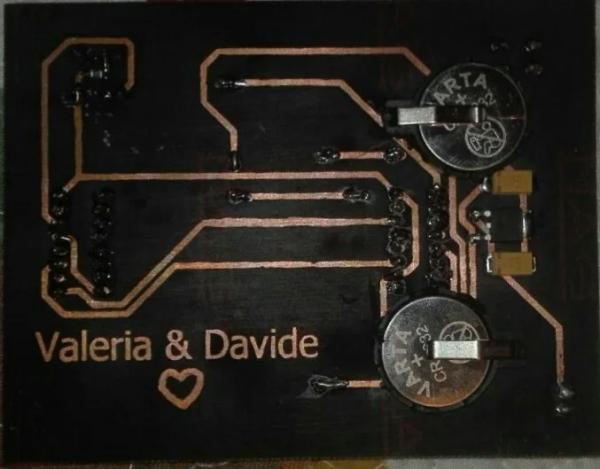
- 2x CR2032 battery holder (For the PCB layout I’ve chosen to put two holes apart from each other with a distance that I’ve measured on the holders that I had on hand. If you have different size holders you can change the PCB easily as I’ll show you later
- 2x CR2032 battery
- 1x Slide switch (choose whatever you want on this, I choose a small through hole one, but an SMD one should to even better)
- 1x Two sided copper clad boar
All this things costed me 15€, which is a lot but I bought them at a local electronics store. For you I’ll put some Digikey links, but you can buy from whoever you prefer!
Digikey Links:
- 100ohm 0805 SMD
- Red LED PLCC2
- 10k 0805 SMD
- LM7805 TO-252
- 0.33uF tantalum
- 0.1uF tantalum
- 74HC595 16DIP
- Attiny85-20PU 8PDIP
- Tactile switch (that’s the exact one that I’ve used, is red like the LEDs)
- CR2032 battery holder
- Slide Switch
Step 2: Eagle Design
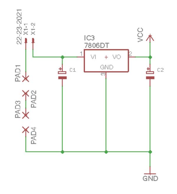
First thing first I took LexanPanda design and I’ve layed the schematic in Eagle: here are all the files.
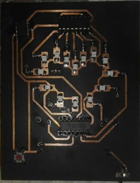
As you can see I’ve made a two side layout, don’t be scared by this, I’ll show you later how I made the PCB with the toner transfer method! There are a lot of guides on the internet, and even on instructables, on how to made two sided PCB with the toner method. Obviously you can use any method you like! For this board I even thought about buying a UV sensible PCB but I didn’t have much time.
There’s a little catch, I’ve said previously in the parts list: I didn’t have time to search or create the eagle file for the CR2032 holder so I’ve simply made 4 pads that on the PCB are a certain distance apart. This distance was measured between the pins, with a caliper, on the CR2032 holders that I had laying around. Feel free to take the board file for eagle and change it to suit your needs! It’s pretty easy and you don’t have to mess around too much with the layout.
Step 3: Making the PCB
Now, if you have all in your hands we can begin to make the PCB! To simplify things I’ll put directly the PDF file that you can print to make your PCB. If you make your own be sure to horizontally mirror the top or bottom side of the board! In my PDF I’ve flipped the top side.
As you can see I’ve put some text in my pdf, obviously you can remove it and put your name along with the one of your mate, or leave it blank, that’s up to you!
Now on how to make a two sided PCB:
After you I’ve printed your layout you have to take the top and the bottom half and make the printed part look at each other. Be sure to leave some room at the side of the print to put some staples next. Than, with the help of some light, align the holes of the ICs, be sure that they’re precisely over each other and when you’re happy, staple the paper in place, or use some tape, leave some space to the copper clad that will be sandwiched between the papers! It’s very important that, after you secure the papers to each other, you check again and again if the holes are aligned. Then put your bare board between the papers being sure that the top and bottom layout align with it. Now it’s time for ironing
After you’ve etched the board put the holes with a 0.8mm drill bit according to the PCB layout, don’t worry if some holes aren’t super aligned, you will be able to solve this problem while soldering.
There are some vias that you need to fill in. I use the legs of through hole resistors that I pass in the vias and solder them on each side.
Be sure to solder both sides of some pins, otherwise the heart won’t work!
Step 4: Arduino Sketch
There’s not too much to say about this, if you want some details go to the LexanPanda instructables.
There are two things that are different from the one he uses: I’ve added some animations, now there are 16 in total, and I’ve added a variable called “multi”, it’s important that you set this based on the speed of the clock that you choose for the attiny85. I’ve chosen 8MHz clock so the variable is set to 8, if you don’t want to change the clock speed, the attiny85 is set by default to 1MHz, the only thing you have to do is to set the variable to 1.
So any speed you choose, set the variable to that speed in MHz steps.
Step 5: Conclusions
So now you have your own LED heart!
I apologize again for the lack of photos, I’ll try to add more In the future! Let me know if there’s anything that I’ve not explained well, or if you want some other details!
Source: Romantic Led Heart SMD
- How can I change the clock speed for the Attiny85?
You must set the variable multi based on your chosen clock speed in MHz steps. - What is the best way to align the top and bottom sides of the PCB?
Align the IC holes precisely using light before stapling or taping the printed layouts together. - Can I use different colored LEDs for this project?
Yes, you can use any color but you must choose the correct resistor value for that specific color. - Does the project require a complex enclosure?
No, the design features a small form factor that looks cool even without an enclosure. - How do I handle vias on the double-sided PCB?
You can fill vias by passing through-hole resistor legs through them and soldering both sides. - What method was used to create the PCB traces?
The author used the toner transfer method with a two-sided layout. - Why are there four pads for the battery holders?
This was done because the author did not have time to create a specific Eagle file for the holders. - Is it necessary to solder pins on both sides of the board?
Yes, you must solder both sides of some pins otherwise the heart will not work.