Summary of Robot Arm Set using Arduino
This article details a DIY robot arm project using an Arduino MEGA 2560 R3 and a Robot Arm Set. The author assembled six servos with wheels and wires, controlled by a 16-channel servo controller powered by a 7.4V Li-Po battery. The process involved wiring the components, testing movements via PC software to determine PWM ranges, and programming cyclic motions for the arm's base, joints, and claw.
Parts used in the Robot Arm Project:
- Robot Arm Set (includes six servos, servo wheels, and extension wires)
- 16-Channel Servo Controller
- 7.4V Li-Po Battery
- Charger
- JST female connector
- Standoff
- Arduino MEGA 2560 R3
- AMS1117 Linear Regulator Breadboard Set
- Switch
I made use of Smart Tank Chassis in the past 4 projects and I wanna do something very different. After searching in google and consider different stuffs for a couple of days, I found the Robot Arm Set. It looks awesome! It provides servos, servo wheels and extension wires so that I can save more time to focus on my project. I can connect it to Arduino and make use of different stuffs together for many combinations!
Step 1: Parts
Robot Arm Set (This set includes six servos, servo wheels and extension wires)
7.4V Li-Po Battery
Charger
JST female connector
Standoff
AMS1117 Linear Regulator Breadboard Set
Switch
* I just make use of the battery and charger in my remote-controlled car for this project. : )
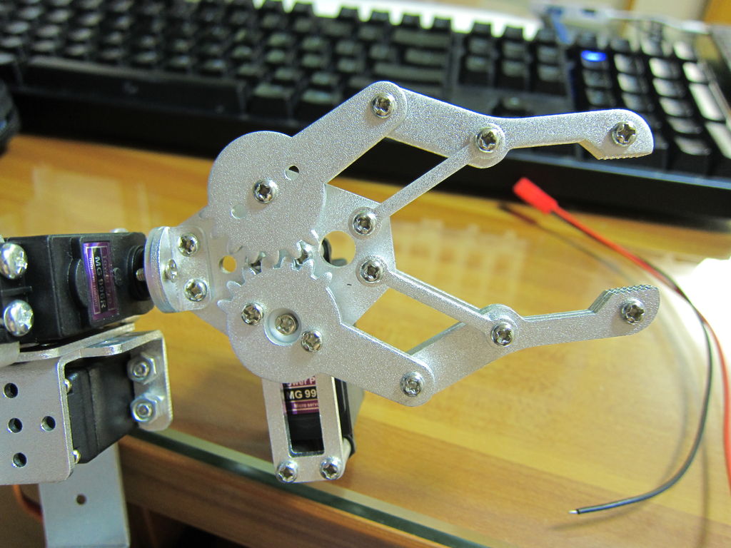
Step 2: Assembly
I guessed it should be very complicated and difficult to finish, but in fact it is not. It is easy to assemble. Just following a few steps in the manual and that’s it!
Step 3: Wiring
I wanna do a test with my PC first before connecting to Arduino. The brown color of the wire in servos represents GND, red is + and orange is for signal. To make it simple I connect the servos from the base to the claw to the servo controller with a sequence from S1 to S6 respectively. Use extension wires if the servo cable is not long enough. Make sure all the cables are in correct direction. I’ve also bundled the wires with plastic cable ties.
The servo controller is fixed at the side of the base with standoff.
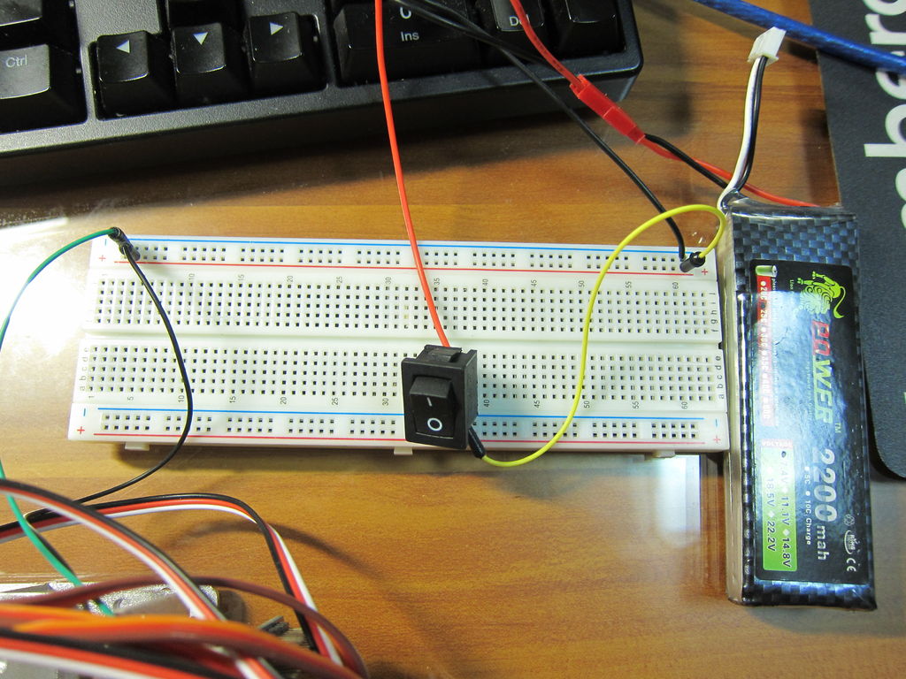
The servos are powered with VS and GND of the blue terminal block on the servo controller, so red wire of 7.4 Li-Po battery is connected to VS and black wire to GND.
For the chip we can either power it up with the pins 5V and GND next to S1, or via USB, or VSS and GND of the blue terminal block. Here I choose USB first. The left green LED is the chip power indicator and the right green LED is the servo power indicator. It is ready if both green LEDs are on. The left red LED indicates data transfer.
Step 4: Test with PC
Next, I install both the driver and the software of this controller to my PC, and connect the controller to PC via USB. Open Device Manager in Control Panel and you can check the COM port of the controller. Then open the software, choose the COM port and click “Connect”. Now I can test the servos by sliding the bars slowly. As the servos react to the bar I slided instantly, if sliding the bars quickly, the servos will move quickly and you may get hurt. Also, don’t slide the bar further if the servo gets stuck already. It is dangerous and the servo may burn out.
During the test I’ve jotted down the maximum and minimum PWM, and the movement of the servos as follow:
Servo Lowest PWM Movement Highest PWM Movement
S1 500 right 2500 left
S2 500 up 2500 down
S3 500 down 2500 up
S4 500 down 2500 up
S5 500 anticlockwise 2500 clockwise
S6 900 open claw 1700 close claw
The PWM of servos are ranged from 500 to 2500, or from 0 degree to 180
degree, at which 1500 represents 90 degree. However, as the degree needed to control the claw is far less than others, to avoid the servo gets stuck, the range of PWM is narrower compare with other servos, from 900 to 1700. The data is for reference only and there may be difference. You are highly recommended doing a test and create this table yourselves.
Step 5: Further testing
Another function of this software is that we can add a series of movements among servos and run it in cycle. After choosing one set of movement, select “Add”, and a set of code appears below “Order”, for example:
#1P1389#2P2P1522#3P922#4P1544#5P1500#6P1567T1000
We can interpret it as follow:
#P<servo number>P<PWM> ………..T<Time>
That means, “1st servo turns to PWM 1389, 2nd servo turns to PWM 1522…… finish in 1000 millisecond (or 1 second).” (This command will be used frequently when connected to Arduino.)
After completing a series of movements, click “Cycle run”. The arm will move continuously according to the sets of movements we’ve added.
For more detail: Robot Arm Set using Arduino
- What components are included in the Robot Arm Set?
The set includes six servos, servo wheels, and extension wires. - How do I identify the wire colors on the servos?
Brown represents GND, red is positive voltage, and orange is for signal. - Can I test the servos before connecting them to the Arduino?
Yes, you can connect the controller to a PC via USB and use the provided software to test servos. - What is the safe PWM range for the claw servo compared to others?
The claw uses a narrower range of 900 to 1700 to avoid getting stuck, while others range from 500 to 2500. - How do I power the servo controller chip?
You can power it via pins 5V and GND next to S1, through USB, or via VSS and GND of the blue terminal block. - What do the green LEDs on the servo controller indicate?
The left green LED indicates chip power and the right green LED indicates servo power. - How can I program a series of movements to run in a cycle?
Use the software to add movement sets which generate code strings containing servo numbers, PWM values, and time commands. - Is assembling the robot arm considered difficult?
No, the assembly is described as easy if you follow the manual steps.