This is my second project for LED Driver based on CAT4101 IC. The first project was for single White LED. This project has been designed to drive 3 channels of RGB LEDs with PWM signal which helps to create multicolor LED light. Arduino Nano is used to generate PWM signal for RGB LED and board has 3 tactile switches and Analog signal input to develop various RGB LED related applications. Each channel can drive load up to 1A and input supply up to 12V DC. 1A X 3 Constant current LED driver shield for Arduino Nano has been designed for verity of LED related applications. The shield provides accurate LED current sink to regulate LED current in a string of LEDs. The LED current is mirrored and the current flowing from the RSET is set by PR1. On board 2W X 3 LED are used for testing purposes. External LED or multiple LED strings can be connected by pulling two wires from the PCB. The PCB has connectors to mount Arduino Nano. Shield also has on board three tactile switches connected to Digital Pins D2,D3 and D12 using pull down resistors pack to be used in any application. On board Trimmer potentiometer PR1, PR2, PR3 helps to set the maximum constant current. PWM input pins are connected to Digital PWM pin D9, D10, and D11 of Arduino Nano to control the LED intensity. CN1 helps to power up the board, CN2 additional connector for Analog A6 input , 5V DC, GND and Reset for some Analog interface applications.
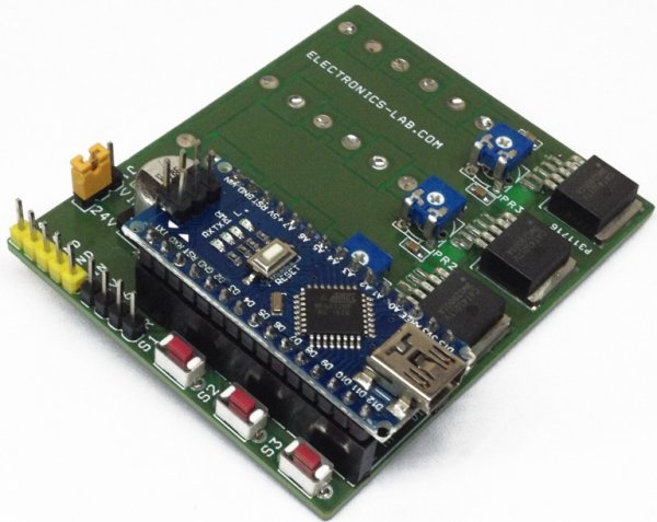
The board is built using 3 x CAT4101 ICs from ON Semiconductor. The CAT4101 is a constant−current sink driving a string of high−brightness LEDs up to 1 A with very low dropout of 0.5 V at full load. It requires no inductor, provides a low noise operation and minimizes the number of components. The LED current is set by an external Trimmer preset PR1, PR2, PR3 connected to the RSET pin. The LED pin is compatible with high voltage up to 24 V, allowing the driving of long strings of LEDs. The device ensures an accurate and regulated current in the LEDs independent of supply and LED forward voltage variation. The PWM/EN input allows the device shutdown and the LED brightness adjustment by using an external pulse width modulation (PWM) signal coming from Arduino Nano D9, D10, and D11 pins. The driver features a thermal shutdown protection that becomes active whenever the die temperature exceeds 150°C.
PWM Duty Cycle and Frequency
Accurate linear dimming is compatible with PWM frequencies from 100 Hz to 5 kHz for PWM duty cycle down to 1%. PWM frequencies up to 50 kHz can be supported for duty cycles greater than 10%.When performing a combination of low frequencies and small duty cycles, the device may enter shutdown mode. This has no effect on the dimming accuracy, because the turn−on time TPS is very short, in the range of 1s. To ensure that PWM pulses are recognized, pulse width low time TLO should be longer the 1s. The CAT4101 enters a “zero current” shutdown mode after a 5 ms delay (typical) when EN/PWM is held low.
Read more: RGB Led Driver Shield for Arduino Nano