I wanted to have an easily programmable RGB light to toss into a Jack ‘O Lantern for Halloween. Who really wants a dull pumpkin in these days of pumpkin pimping madness. So I set to work building a pocket tin sized RGB lamp that could be reused after Halloween for some other RGBing need. The goal, that it could fit into a tin with room to spare for possible future additions, that it be hyper-simple to write up a new light show. That it used an Arduino at its heart, because I am familiar with them and they are fun.

So lets get to making something!
If you are here for the library it is in step 3. Go on then, let then others read quietly.
Step 1: Gather up your kit
To build a replica of my pocket RGB lamp, you will need….
A RGB LED..(You can get these at most electronics stores/sources)
An Arduino Mini Pro 5v (Available from Sparkfun and Robotshop and a bunch of other places too)
A good pocket sized tin that can house a 9v battery and some stuff. I used an alternative to the minty fresh choice of many a maker. Mine, while lacking in freshness is both sharp and precisely engineered…or so I am lead to believe….Your tin will be fine, don’t get tin envy…honestly it is only a tin.
A small protoboard, or a larger one that you don’t mind cutting to make a smaller piece.
3 resistors, I went with 330ohms. Usually a safe bet with LEDs, but if you have your datasheet, and options, do the math…V=IR is a good place to start.
A 9v battery connector
Some female headers (available at many online retailers)
a small on/off push-button (Dollarama is a great place to find stuff like this attached to other stuff that is also often useful)
Some bits of hookup wire.
some thin foam or thick paper or something to line the bed of the tin in to keep it from shorting out anything.
A small credit card Fresnel magnifier. Not strictly necessary, but I like excuses to cut up credit card sized Fresnel lenses.
ummm…a drill, a computer….ummm…thats it I think.
Okay have you gathered your gear? Do a dry fit. Put the board and battery in the tin, place other components on top, close tin. If the test goes well, proceed to next step, otherwise, figure out what is going to be the problem and then find a slightly larger tin.
I had to cut a bit of my protoboard off. A quick way to do this if you don’t mind a rough cut is to score a line and snap it off.
Step 2: Solder up your board
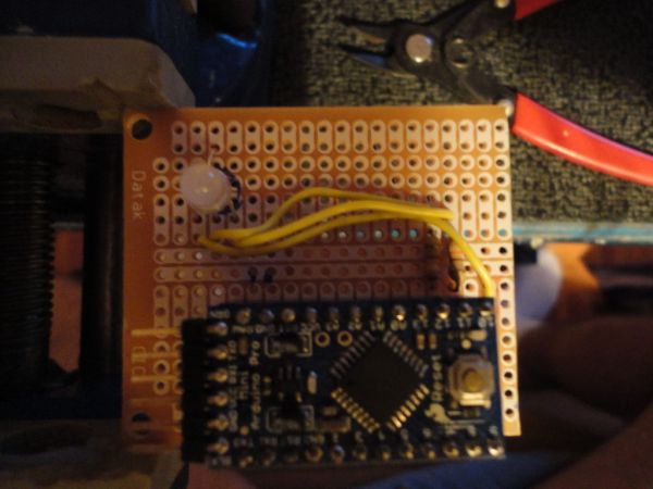
Start by sliding your female headers onto your Arduino mini and positioning the whole thing on your protoboard. This ensures that everything mates nicely at the end, you can just solder the headers in, but if they sit a little off of square, it makes a rougher socket fit.
Make sure you don’t have pins overtaking the perimeter of the board, as these could make contact with the tin and short the circuit.
Position your RGB LED as well, somewhere that gives you a little room to work, there is loads of real estate available. I placed mine so it would sit roughly centered in the length of the tin.(see the little pen mark, I scratched that on during my dry fit)
A little piece of electrical tape on each bit helps to hold it in position when we flip it over to solder.
Do that next, solder it up and get rid of the tape, clip your excess leads. Another trick is to stick your lead clippings to your discarded bit of tape, stepping on a lost one hurts.
Next, run one resistor each off of pins 9, 10, and 11. Use some wire and run from the other end of the resistor to the anodes of your RGB LED. You will want pin 9 connecting to the red anode, pin 10 to green and pin 11 to blue if you plan on using the little Moodlamp Library I have included. Again, that’s 9 to red with a resistor, 10 to green with a resistor, 11 to blue with a resistor. Solder the cathode out to an empty area on the board. (Don’t worry, we’ll ground it soon)
Solder an on/off button in a place that you find appealing. Run a wire from ground on the Arduino mini to the cathode of the RGB LED. Then connect the positive of your battery connector to the other button terminal, and the negative to your little grounding zone. (where the cathode from the LED ends)
Snip your leads and inspect your soldering job before applying power.
An Arduino Mini Pro 5v
A small protoboard
For more detail: RGB lamp with Custom Moodlamp Library using Arduino