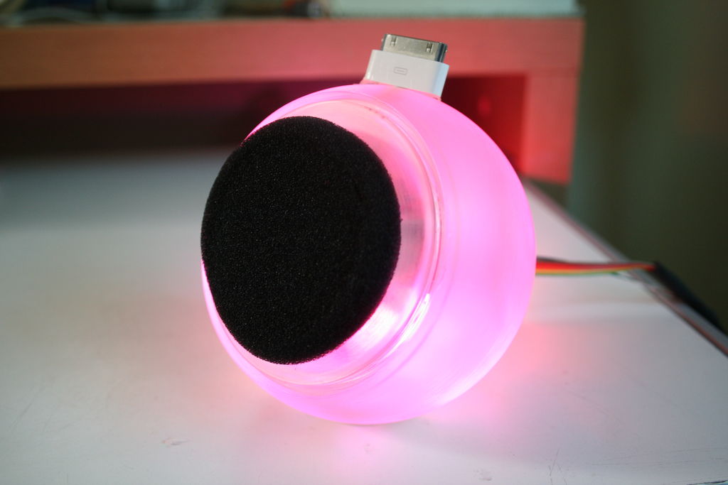
Using an Apple Pro speaker, I made a flashing RGB LED iPod dock for about $35.
I recommend reading the entire ‘ible before starting. Also, note that the volume is control from the iPod.
It consumes minimal power in shutdown mode, and is controlled by a Teensy.
This took me ~3 days to build, and you should know how to solder pretty well before doing this project.
The enclosure looks amazing when lit, it is really fun to watch it.
Step 1: Gather Tools & Materials
Tools:
Soldering Iron
Hot Air gun/Hair dryer
Hot glue gun/epoxy
Drill (or dremel)
Screwdriver
Sandpaper (fine grit)
Wire strippers
Soldering Iron
Hot Air gun/Hair dryer
Hot glue gun/epoxy
Drill (or dremel)
Screwdriver
Sandpaper (fine grit)
Wire strippers
 Parts:
(1) Teensy 2.0
(1) Sparkfun RGB LED breakout
(1) Sparkfun Mono Audio amp breakout
(1) Apple pro speaker (You only need one speaker, not the set)
(1) Mini-USB cable (will be cut up)
(1) iPod-USB cable (also will be cut)
(1) Audio plug
(1) Push-on/Push-off button
(1) 10K ohm resistor
(1) Roll of solder
(1) Headphone foam cover (black foam circles found on old headphones, I had a few lying around.)
Assorted heat shrink
Ribbon cable or other thin wire
Step 2: Disassemble the speaker
To open the apple pro speaker, unscrew the three screws around the rim of the speaker. Remove the speaker and cut the wires. Keep the speaker aside, and pull the thick white wire out of the speaker. Discard it. Save all three screws.
Step 3: Drill and sand the speaker
Drill a hole as large as the iPod cable into the top center of the speaker. Drill slightly fast or the plastic will crack. Then, using a thinner bit, remove all the foam/stuff from the metal hole where the wire used to come out of. Drill until you can slide 7-wire ribbon cable inside.
Remove the ribbon cable, and sand with fine grit paper until the enclosure is smooth, translucent, and will blend light well.
Remove the ribbon cable, and sand with fine grit paper until the enclosure is smooth, translucent, and will blend light well.
Step 4: Connect +5v and GND to everything.
Take your iPod cable and cut it ~2″ from the iPod connector. Take the iPod side and push it through the hole you drilled on the top. Using wire strippers, carefully remove 1/2 centimeter of the outer white insulation. There will be 4 wires, and the braided shielding. move the braided shielding to the side and cut it off. Strip the green and white wires, and twist them together. Solder. Strip the red and black wires, and solder two pieces of ribbon cable to them (Make sure that the red and black are not in contact). Those are the power and ground. Heatshrink all your connections. Take your Mini-USB cable and cut it ~2″ from the mini side. Put that aside for now. Take your Teensy, and solder a wire from the Vcc and GND pins (left and right of the USB jack) to the corresponding Vcc/GND that you just soldered to the iPod wire. Remember, this is all inside the apple pro enclosure. DO NOT HEATSHRINK THIS CONNECTION yet. Take the Sparkfun audio amp and solder two wires to its Vcc/GND pins. Connect the other ends to the connections you made between the teensy and the iPod connector. (We’ll call these the Vcc and GND “hubs”). Take your Sparkfun RGB breakout, and assemble it. (Instructions)
Solder 5 wire ribbon cable to the output pins. Leave the three R/G/B wires alone, and connect Vcc and GND to our “hubs”. Now that the hubs are finished, you can put some heatshrink over the top and shrink!
Solder 5 wire ribbon cable to the output pins. Leave the three R/G/B wires alone, and connect Vcc and GND to our “hubs”. Now that the hubs are finished, you can put some heatshrink over the top and shrink!
Step 5: The LED’s and Speaker
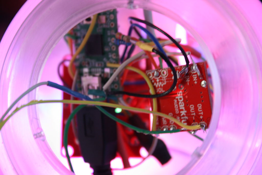
Looking at this Teensy pinout, I see that pins 12, 14, and 15 are PWM pins. PWM is a way to change brightness with a square wave. For more in-depth description of PWM, go to the Arduino page. Solder the R/G/B wires to the pins 12, 14, and 15. Now, solder two wires to the speaker. Solder them to the sparkfun audio amp’s OUTPUT wires. Polarity is unimportant. Take a 7-wire piece of ribbon cable (about 6″ long) and push it through the silver hole in the back. Take the Mini-USB side of the cable we cut earlier, and plug it into the teensy. Strip 1/2 cm of insulation. There will be 4 wires, and a braided shielding. I decided not to connect the braided shielding. The shielding stops possible EMI or any kind of static. My device works without it. So, cut the shielding off. Connect all four wires (red, black, green, white) to wires in the 7-wire ribbon cable, solder, and heatshrink. Then solder two wires to the INPUT of the audio amp. Solder the other end to two more of the ribbon cable wires.To recap: The speaker is connected to the OUTPUT of the amp, The 4 Mini-USB wires and the INPUT of the amp are connected to 7-wire ribbon cable leaving one wire, The RGB leds are connected to PWM pins, and the mini-USB is plugged into the teensy.
For more detail: RGB flashing iPod dock from an old speaker