I was having a discussion with my other half about football and money and the subject came round to betting. Whenever he goes to the match his mates all chip in a few quid and they put a bet on. The bet is usually the final score AND either the first or last goal scorer. Needless to say they never win any money.
We decided to make that money work for us instead – so we will enjoy the excitement of a bet while saving money.
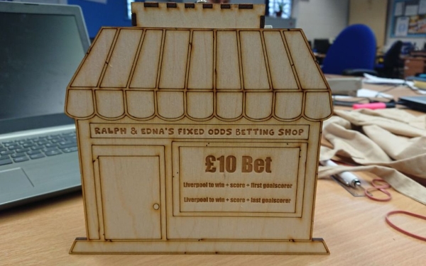
Introducing Ralph & Edna’s Fixed Odds Betting Shop (named after Edna Cross and Ralph Hardwick from Brookside – they loved having a cheeky little bet)!
Both of us will place a £10 bet on a randomly generated final score AND first or last goalscorer. If either of us win, we win £20. If we lose, the money goes into a savings box. At the end of the football season we’ll use whatever we have to go on holiday or something. There’s still a small chance one of us will win some money each week, but the house definitely wins most of the time – just in our case the house is ours so we win either way!
So I wanted to make a money box that represents the betting shop. And I want to include a button that, when pressed, will display the random bet each of us is making.
Step 1: for This Make I Used:
- Arduino
- LCD1620 screen
- Header pins
- Breadboard
- Male to female jumper wires
- Male to male jumper wires
- Female to female jumper wires
- Push button
- 220 ohm resistor
- 3mm plywood
- 2 M3 bolts
- 3 M3 nuts
- 2 zip ties
- Velcro strips
- Prototyping board
You’ll also need access to:
- Soldering iron
- Laser Cutter
- Scissors
Step 2: the Circuit
Solder the pin header to the LCD1602
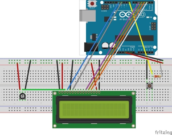
Assemble the Arduino and screen on a breadboard as follows:
From the LCD screen:
- Both end pins (VSS & K) go to ground and the next pins along (VDD & A) go to 5V
- VO goes to the middle pin on the potentiometer
- RS goes to Arduino Digital Pin 12
- RW goes to ground
- E goes to Arduino 11
- D4 goes to Arduino 5
- D5 goes to Arduino 4
- D6 goes to Arduino 3
- D7 goes to Arduino 2
The push button:
- Connect the resistor between the positive leg and 5V
- Connect ground leg to ground
- Connect positive leg to Arduino 8
The potentiometer
With the turner facing you the left pin goes to 5V and the right pin goes to ground.
Finally
Connect the breadboard positive and negative rails to the Arduino 5v and Gnd pins.
Step 3: The Code
Connect the Arduino to a computer and log in to the online Arduino web editor or use the IDE to create a new sketch. Copy and paste this code and upload it to the Arduino.
include
LiquidCrystal lcd(12, 11, 5, 4, 3, 2);
char * scores [] = {“1-0″,”2-0″,”3-0″,”4-0″,”5-0″,”2-1″,”3-1″,”4-1″,”5-1″,”3-2″,”4-2″,”5-2″,”4-3″,”5-3″,”5-4”};
char * goaltime [] = {“First”,”Last”};
char * player[] = {“Salah”, “Firmino”,”Mane”,”Shaqiri”,”Milner”};
long betscore;
long bettime;
long betplayer;
// constants won’t change. They’re used here to set pin numbers:
const int buttonPin = 8; // the number of the pushbutton pin
// variables will change:
int buttonState = 0; // variable for reading the pushbutton status
void setup() {
lcd.begin(16, 2);
lcd.clear();
}
void loop() {
pinMode(buttonPin, INPUT);
buttonState = digitalRead(buttonPin);
betscore = (random(sizeof(scores)/sizeof(char))); bettime = (random(sizeof(goaltime)/sizeof(char)));
betplayer = (random(sizeof(player)/sizeof(char*)));
if (buttonState == LOW) {
lcd.clear();
lcd.setCursor(0, 0);
lcd.print(scores[betscore]);
lcd.setCursor(0, 1);
lcd.print(goaltime[bettime]);
lcd.setCursor(6, 1);
lcd.print(player[betplayer]);
delay(5000);
lcd.clear();
}
else {
lcd.setCursor(0, 0);
lcd.print(“LFC to win:”);
}
}
Step 4: Casing & Assembly
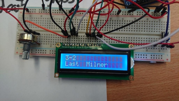
Assuming it all works you can move on to making a casing for it.
Cut the design using a laser cutter.
While using the breadboard you probably used male to male jumper wires. We can now attach wires directly to the pin header on the screen using male to female wires. We can also connect the potentiometer to the screen using a female to female wire.
I used 2 pieces of prototyping board and soldered all the ground wires to one and all the 5V wires to another, ensuring there was a connection between all the wires. Remember the resistor also connects to 5V so you may need an extra wire between the resistor and the prototyping board.
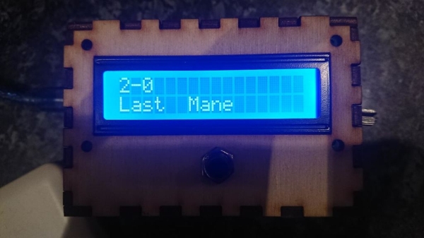
Plug in the Arduino again to make sure it is all connected and working and then assemble the box.
- I started with sticking the USB socket through the square hole on the side panel.
- Push the button through the round hole on the top piece and the LCD screen through the large rectangle hole.
- If there’s a nut for the push button add this to the front to secure it in place.
- The screen should be a snug fit so won’t require screwing.
- The hole on the remaining side panel is for the potentiometer.
- Glue all the side pieces together with the base and then carefully bundle together all the wires and fit them into the space before adding the lid. Do not glue this in place as you may need to access the wires inside in future.
- If the wires push the lid up secure it with elastic bands.
Plug the Arduino in and check it’s still all working….
Source: Random Bet Generator Money Box