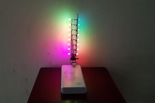
Today I would like to share how to make a sculpture circuit that controls 16 RGB leds using ATTINY85. We can adjust their colors separately according to the colorwheel rule with a touch button.
Step 1: Things We Need
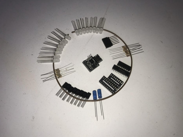
The main components are as follows:
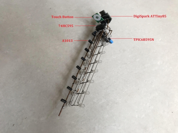
- 1pcs x DigiSpark ATTiny85.
- 1pcs x Shift Register 74HC595N.
- 1pcs x Power Logic 8-Bit Shift Register TPIC6B595N.
- 8pcs x Transistor A1013.
- 16pcs x RGB LED 5mm, Common Anode.
- 6pcs x R100.
- 8pcs x R1K.
- 2pcs x Capacitor 0.1uF.
- 1pcs x 2.54mm Pitch 40 Long Pin Single Female Header.
- 1pcs x 16-Pin DIP IC Base Socket Connector (For 74HC595N).
- 1pcs x 20-Pin DIP IC Base Socket Connector (For TPIC6B595N).
- 1pcs x Touch Button.
- 1meter bare copper wire.
- 1pcs x Power Bank 5V.
Tools:
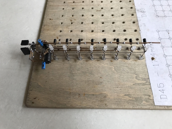
- Wooden template: I reused a template when I did a led cube project. For this project, we just need one row with 8 holes, each hole diamter: 5mm and hole spacing: 20mm.
- Soldering Iron: I use 2 types of soldering iron, one with a small tip and adjustable temperature and the other with a bigger tip. The reason is that my small tip soldering iron is very difficult to solder big size bare copper wires together.
- The other tools
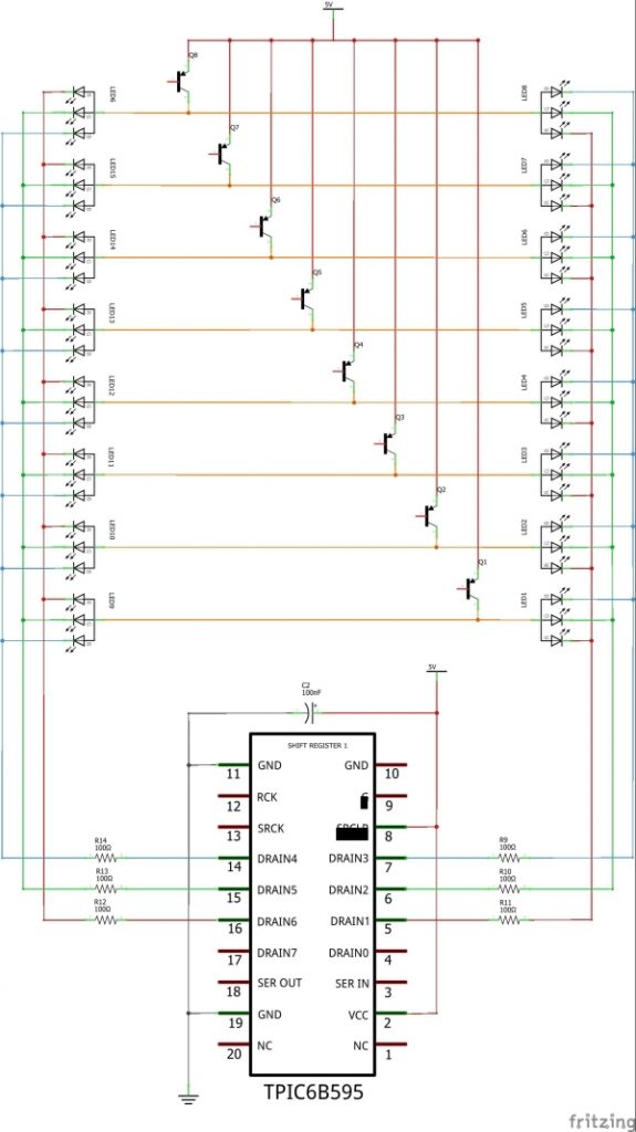
Step 2: Schematic
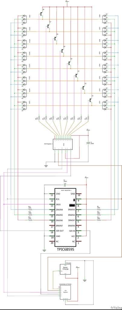
The project schematic is shown on the above picture. I try to arrange the schematic as same as the circuit sculpture arrangement so it is quite big. You can download HERE for schematic in PDF file.
Step 3: Soldering Works
Soldering the red, green, and blue pins (cathode pins) of 8 leds together to form the first group.
Soldering the same for second group and arrange two groups of leds with their backs to each other. The anode pins are soldered together.
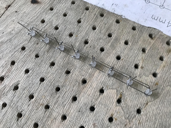
Identifying the E (Emitter) pin of PNP A1013 transistor. These pins will be connected to the power supply. I inserted 8 transistors into the wooden template holes and soldered all E pins to the copper wire. The C (Collector – middle pin) pins of each transistor will be connected to the led group anode pin above. Because transistors and LEDs have the same spacing, it is easy to solder.
Once the C pin (Collector – the middle pin) of the transistor is connected to the anode pin of the led, I had a strong structure. Then I soldered remaining components and fly wires following the schematic. I can put leds into wooden template holes
Or I can put transistors into wooden template holes during soldering.
We need to note the pinout and arrangement of the 74HC595.
And TIPC6B595N pinout and its arrangement .
Because it is symmetrically arranged so it can stand on its own on a flat surface.
Step 4: Programming
1. The project code is available at my GitHub.
2. The following core, library need to be installed in this project:
- ATTinyCore at: https://github.com/SpenceKonde/ATTinyCore
This core allows sketches to be uploaded directly to DigiSpark ATTiny85 via USB and it can be installed using the Boards Manager in Arduino IDE. The Boards Manager URL is:
http://drazzy.com/package_drazzy.com_index.json
– File ‣ Preferences on Arduino IDE, enter the above URL in “Additional Boards Manager URLs“
– Tools ‣ Boards ‣ Boards Manager… – Select “ATTinyCore by Spence Konde” and click “Install“.
- tinySPI library at: https://github.com/JChristensen/tinySPI
– Open Aduino IDE
– Sketch ‣ Include Library ‣ Manage Libraries… ‣ Search “tinySPI by Jack Christensen” ‣ Install.
3. Programing Notes:
In this project, DigiSpark ATtiny85 carry out SPI protocol to control 16 x RGB Leds, the pins are used as below:
- DigiSpark ATtiny85 P0 (PB0) – LATCH PIN OF TPIC6B595N & 74HC595N
- DigiSpark ATtiny85 P1 (PB1) – DATA PIN OF TPIC6B595N
- DigiSpark ATtiny85 P2 (PB2) – CLOCK PIN OF TPIC6B595N & 74HC595N
- DigiSpark ATtiny85 P3 (PB3) – BLANK PIN OF TPIC6B595N & 74HC595N
- DigiSpark ATtiny85 P4 (PB4) – TOUCH BUTTON.
SPI hardware or software can be defined via:
#define HARDWARE_SPI 1 // set to 1 to use hardware SPI, set to 0 to use software SPI
To set the address and color of each led, I used this subroutine:
void LED(int X, int Z, int R, int G, int B)
{
  X = constrain(X, 0, 1);
  Z = constrain(Z, 0, 7);

  R = constrain(R, 0, 15);
  G = constrain(G, 0, 15);
  B = constrain(B, 0, 15);

  byte WhichBitRed[2]  = {1, 6};
  byte WhichBitGreen[2]= {2, 5};
  byte WhichBitBlue[2] = {3, 4};

  for (byte BAM = 0; BAM < BAM_RESOLUTION; BAM++)
  {
    bitWrite(RRGGBB[BAM][Z], WhichBitRed[X], bitRead(R, BAM));
    bitWrite(RRGGBB[BAM][Z], WhichBitGreen[X], bitRead(G, BAM));
    bitWrite(RRGGBB[BAM][Z], WhichBitBlue[X], bitRead(B, BAM));
  }
I only used one TPIC6B595N for all led cathode scanning, we can see detail connection in picture below:
- Red pin in right group – DRAIN 1
- Red pin in left group – DRAIN 6
- Green pin in right group – DRAIN 2
- Green pin in left group – DRAIN 5
- Blue pin in right group – DRAIN 3
- Blue pin in left group – DRAIN 4
That why we can see these below commands in the program. They are used to identify led pin address (X) corresponding to each layer (Z):
byte WhichBitRed[2] 	= {1, 6};
byte WhichBitGreen[2]	= {2, 5};
byte WhichBitBlue[2] 	= {3, 4};
For anode scanning, I used an array to store the 8 layers and the specific layer will be shifted out via 74HC595N from this array element.
byte anode[8]= {B11111110, B11111101, B11111011, B11110111, B11101111, B11011111, B10111111, B01111111};Source: Rainbow Led Circuit Sculpture