When we’re working with LEDs, we often like to control their state (on/off), brightness, and color. There are many, many different ways of going about this, but none are as compact a solution as the WS2812 RGB LED. In its tiny 5mm x 5mm package, the WS2812 includes 3 super bright LEDs (Red, Green, and Blue) and a compact driver circuit (WS2811) that only requires one data input to control the state, brightness, and color of the 3 LEDs.
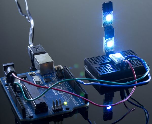 At the expense of needing only one data line to control 3 LEDs, there comes a demand for highly precise timing in the communication with the WS2811. For this reason, a real-time microcontroller (e.g., AVR, Arduino, PIC) is required. Sadly, a Linux-based microcomputer or an interpreted microcontroller such as the Netduino or Basic Stamp cannot provide the sufficient timing accuracy that is needed. And so, in this Instructable I walk through the process of setting up, and controlling one of these LEDs with an Arduino Uno. Then, I show how easy it is to connect several of them together for an awesome lighting display!
Difficulty level: Beginner
Time to completion: 10-15 Minutes
Step 1: List of Materials
This wonderful RGB LED comes in a 5050 (5mm x 5mm) package with 6 pads that are fairly easy to solder onto a breakout board. As the only additional component needed is a de-coupling capacitor, the WS2812 honestly offers the best solution for controlling color and brightness of an RGB LED. The embedded constant-current LED driver (WS2811) is remarkably useful for two reasons:
– A constant current of ~18mA will drive each LED even if the voltage varies.
– There is no need to add current-limiting resistors (a.k.a choke resistors) between the power supply and the LEDs.
All we need is a very simple design to provide Power, Ground, and 1 Control Input in order to create an awesome lighting display consisting of not one, but a whole array of RGB LEDs. That’s right! By connecting the Data Out pin of one of these LEDs, to the Data In pin of another, we can drive them both independently with the same Control Input! If it’s not obvious how to do this, do not be troubled, by the end of this Instructable you’ll be well on your way to adding WS2812 to any project you want!
For this Instructable here’s a what we’ll be using:
Materials:
3 x WS2812 RGB LEDs (pre-soldered onto a tiny breakout board)
1 x Solderless Breadboard
Solid Core Wire (assorted colors; 28 AWG)
1 x Arduino Uno R3
1 x Break-away Pin Connector, 0.1″ Pitch, 8-Pin Male (Right-Angle)
1 x Pin Connector, 0.1″ Pitch, 8-Pin Female (Right-Angle)
1 x Breakaway Pin Connector, 0.1″ Pitch, 8-Pin Male
PC
USB A/B Cable
Wire Stripper
Soldering Iron
Notes:
Depending on your project, the WS2812 RGB LEDs are also available without a breakout board for about $0.40 each, but the convenience of the pre-soldered option is attractive for simple applications.
Step 2: Connecting the pin headers
With all the materials listed in the previous step, it is quite straight forward to light up a WS2812 RGB LED.
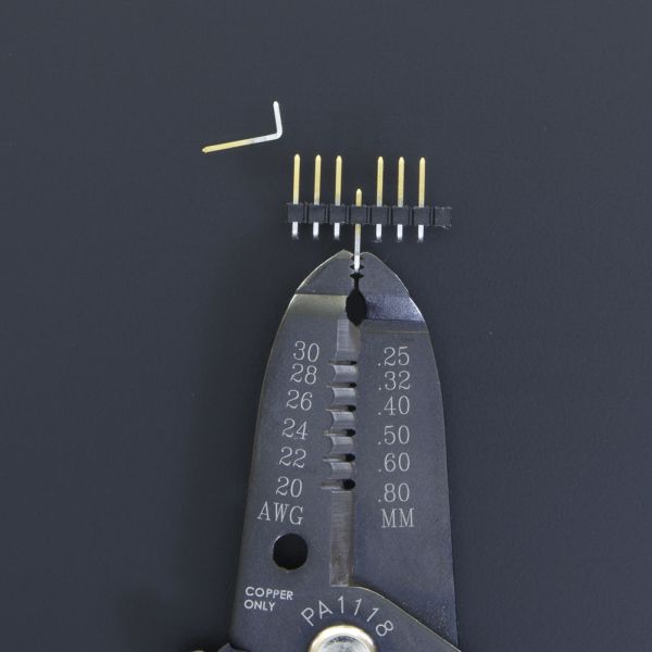
First, we want to prepare the WS2812 Breakout Boards for placing them on the solderless breadboard. To do this, we use a wire cutter (most common cutting tools will work just as well) to separate each 8-Pin strip into 2 x 3-Pin pieces. Keep in mind that making the cut is a little tricky; often times I’ve tried to use the groove between two male headers as a guide for the cut, and I’ve ended up shearing too much plastic off a header I meant to keep.
By ‘sacrificing’ the pin where we want to make the cut, we avoid the problem altogether. Using a pair of pliers, we pull off the pin where we want to cut (in this case, the 4th and 8th pin). After the pins have been removed we can easily cut down the middle of the now-empty headers. This technique works equally well with the female header.
After prying and cutting, we should have 6 x 3-Pin headers, that is, 2 x standard and 4 x right-angle (2 x male, 2 x female). With the help of a soldering iron, we can now connect the pins to each of the three breakout boards in the following way. One board should have the 2 x standard headers, whereas the other two boards should each have 1 x right-angle header.
On the board that’ll have the standard pin headers, we place the pins on the bottom surface of the board (the side opposite to where the LED is). On the other two, the right-angle headers (one of each gender) can be placed either on the top or bottom surface. Note that it’s important to be consistent, from one board to the other, on the placement of the male and female headers. It is helpful to use the surface mount capacitor for orienting the boards; using this as reference, the male header should be soldered to the end closest to the capacitor.
Once the pins are soldered, we are ready to connect one of them to the Arduino!
Step 3: Connecting the WS2812 Breakout Board to an Arduino
In this step we’ll make the necessary connections between an Arduino, and one of our WS2812 Breakout Boards. For this purpose we’ll use the solderless breadboard, and 3 x jumper wires. If you’re using a spool of wire, now is the time to cut 3 pieces, each about 4″ long.
We can now place the WS2812 Breakout Board (the one with the standard headers) across the divider of our breadboard.
Making sure that the Arduino is disconnected from both a power source and USB, we’ll proceed to wire up the connections. On the underside of the WS2812 Breakout Board we can find the name of each pin: VCC, DI (DO), GND. Using this as a guide we proceed to connect the 5V and GND pins from the Arduino to the VCC and GND pins of the WS2812 board, respectively. Then, we connect pin 8 on the Digital side of the Arduino to the DI pin of the WS2812 board, which is the center pin of the side closest to the capacitor.
Now we’re ready to load our program to the Arduino, and make the WS2812 blink!
Step 4: Making it blink with the Arduino IDE
I’ll assume you’ve already installed the Arduino IDE to your computer—plenty of guides on the web explain the process quite well.
The program we’ll need to load to our Arduino can be download here. After we can simply double-click the primer.ino file inside the firmware > examples> primer folder to load it onto the Arduino IDE (wirtten for version 1.0.5). The package includes the necessary libraries for the code to compile so there shouldn’t be any errors, please post a comment if you do encounter any problems compiling. After selecting the Arduino board type, and USB port using the Tools menu option, upload the code, and the WS2812 should start blinking alternating between Red, Green, and Blue.
The neatest feature about these WS2812 RGB LEDs is that they can be ‘daisy-chained’ fairly easily to create long strips and arrays containing many of these LEDs. In the next step we do precisely this with the 3 boards we’ve prepared.
For more detail: Best RGB LEDs for any project (WS2812)