Intro
What does one do when designing a power supply? Well, build a power supply tester, of course. One of the simplest things to build is a constant current load. This will allow for testing of the endurance of the power supply, as most of the designs out there are using slow components.
However, I wanted to make a better one: one that I could hook up to my Analog Discovery and generate a test waveform to be able to connect and disconnect the load fast. This is a weekend project, so all parts are not the best for the purpose, just what I had around.
Warning: The analog discovery is grounded through your PC (unless using a laptop on battery only) so you have to make sure that both the supply being tested and the auxiliary 12V supply are isolated and not grounded. Or use an isolated aux supply and a USB optical isolator if the supply under test is grounded.
Update: Check the PSU Burner being tested with a real power supply in my PeakTeck 6225A review.
Take 1
The simplest of design, one OP-AMP driving 3 MOSFETs. All fine until I made a mistake: with the signal generator connected and turned ON, i connected a 24V 5A supply that was already on, while the signal generator was providing a square wave for 5A current. This caused one of the MOSFETs to blow up (shorting) due to an avalanche event. Finally the power supply went into hiccup mode.
Have you ever seen a fuse pulsating? With the output of the supply shorted and the fuse quite at the limit of the current, it is almost melting each time the power supply tries to restart
Take 2
There are some improvements, so let’s go through the schematic first. The way it works is simple: U1A will drive Q1 such that the voltage across R6 is equal to the reference at it’s positive input. This in effect creates a constant current being drawn from the test power supply.
In “external mode” the constant current load is controlled and read out by the Analog Discovery. Since the control signal can be up to 5V, with R5 being 0.1Ω, I have divided it 10 times using R2-R3, to limit the max current to 5A. In “internal mode” there is a fixed reference generated using RV1 and a 5V regulator, which makes the supply draw a constant, adjustable current.
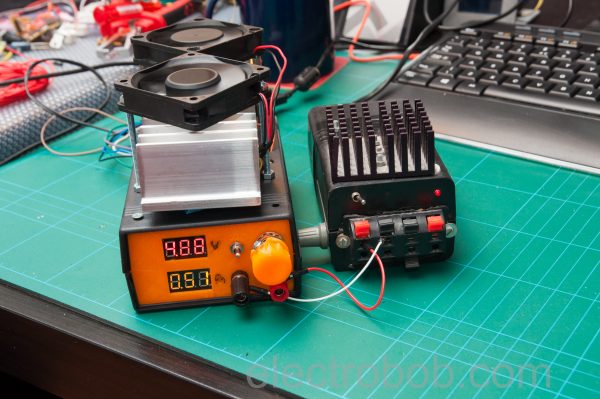
For a nicer look, I added 2 meters, they are your typical 3 wire voltmeters, but make sure you get the nicer ones which auto-scale and use all 3 digits for precision under 10V which are also hackable. The current meter needs a 10X amplifier first, since we are reading current on a 0.1Ω resistor.
Read more: PSU Burner – a power supply tester