
Summary of Project: Car Speed Detector Using Arduino
This article details a car speed detector project using an Arduino Nano and two IR sensors. The system measures vehicle speed by calculating the time taken to travel a fixed distance between the sensors, utilizing interrupts for efficiency. Results are displayed on a 16x2 LCD screen. The setup relies on the formula Speed = Distance ÷ Time, requiring precise calibration of the sensor spacing for accurate readings.
Parts used in the Car Speed Detector Project:
- Arduino Nano
- IR Sensor (2 units)
- 16X2 LCD Display
- 12 Volt Power Adaptor
- DPDT Switch
- LM358 Operational Amplifier IC
- Preset (for contrast control)
Car speed Detector Project
In this project I am going to show you how to measure the speed of running car (or man) from outside. Police department uses this type of system to prevent over speed of vehicles. Our project is a little different from the system used by police but the overall car speed detector concept is same.
In this project, two IR sensors are placed apart on one side of road. When any vehicle crosses the sensors, the internal timer of Arduino counts the time between activation of sensor. Now speed is measured by using simple distance time relationship.
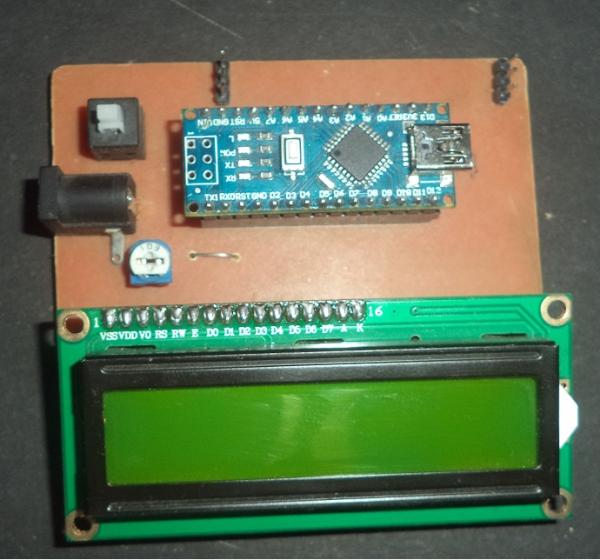
Working
Both IR sensors are connected to the interrupt pin of Arduino, and they detect the falling wave. The purpose of using interrupt is that, it improves the efficiency of system. A LCD is connected to Arduino and measured speed is shown on LCD.
When car moves in front of the first sensor, it gives the output signal to Arduino, Arduino detects the falling wave, now internal timer of Arduino is started and when car moves in front of second sensor timer is stopped.
Now Arduino measures the speed of car which is measured by distance time relationship
Speed = Distance ÷ Time
- Speed: Car’s speed
- Distance: Distance between sensors
- Time measured by Arduino
IR Sensor:
The IR sensor includes an IR LED and a phototransistor. When an object passes between the sensors, light reflects from the object and falls on the phototransistor. An operational amplifier IC (LM358) is used and the phototransistor is connected to it. When object come in front of sensor, it sends a logical HIGH signal to Arduino.
Arduino:
An Arduino Nano is used as the controlling unit, You may use any other Arduino variants according to your choice.
Components Used
| Component | Specification | Quantity |
|---|---|---|
| Arduino | Nano | 1 |
| IR Sensor | 2 | |
| LCD | 16X2 | 1 |
| Power Adaptor | 12 Volt | 1 |
| Switch | DPDT | 1 |
Car Speed Detector Circuit
Circuit diagram is shown in the figure below. If you are going to make circuit on breadboard or general purpose PCB (or Zero PCB), the figure below is useful.
For PCB etching,
In the Arduino pins D2 and D3 are interrupt, where D2 is INT0 and D3 is INT1. Output pins of the IR sensors are connected to these pins.
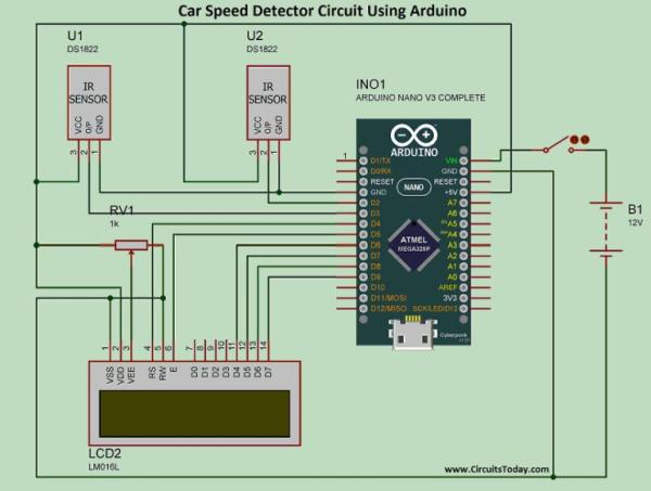
LCD is connected to Arduino’s D4 to D9 pins, where D4 is connected to EN, D5 is connected to RS and D6 to D9 of Arduino are connected to D4 to D7 pin of Arduino. A preset is connected to third pin of LCD, which is contrast control. Pin 15 and 16 are used for backlight of LCD.
Video
Program/Code
At the beginning of the code a header file is declared by name “LiquidCrystal.h”, which is used for LCD display. In the next line pins of LCD are declared in the function “LiquidCrystal lcd(4,5,6,7,8,9)”, number in the bracket shows the pins of Arduino that are connected to the LCD.
In the line 4 and 5 two integers are declared by the name sensor1 and sensor2, these are pins of Arduino pins which are connected to IR sensors.
After it 4 integers are declared by name Time1, Time2, Time, and flag. Where “Time1” is the measured time when “sensor1” is activated and “Time2” is the measured time when “senaor2” is activated. The integer Time is the difference of “Time1” and “Time2”, which is equivalent to time taken by car to go from “sensor1” to “sensor2” or “sensor2” to “sensor1”
Now a float is declared by name “Speed” that is measured speed of the running car.
At the starting of “void setup()” two interrupts are attached by function “attachInterrupt(0, fun1, Falling)” that means when “interrupt0 (INT0)” detect the falling wave, fun1 will run.
Now the LCD is begins by using “lcd.begin(16,2)” function. LCD is cleared by using the “lcd.clear()” function and “SPEED MEASUREMENT” is printed on the LCD by using function “lcd.print”
In the “void fun1()” will run when “interrupt0 (INT0)” activated, in this function current time is measured by using “Time1 = millis()”. After it an “if else” condition is used, it makes the “flag” 1 when it is 0 and makes 0 when it is 1.
After it “void fun2()” is used, that is the exact same as “void fun1()” but it runs when “interrupt1 (INT1)” is activated.
In the “void loop()” first of all Time is measured by using “Time1” and “Time2”, the “Time” should be positive so “if else” is used for making it positive. But this loop runs when flag is equals to zero so an “if” condition is used. If “Time1” and “Time2” are equals “Speed” will be zero.
In the line 47 an condition activated when speed is equals to zero, at this time “….OK….” is printed on second raw of LCD, that indicates, system is ready to use.
In the line 51 speed is printed on LCD after printing “Time1” and “Time2” will become zero.
calibration
In the measurement of speed distance, time relationship is used. So distance between sensors is very important, so we need to calibrate the system.
In the line an integer is declared by name distance that is equal to 27, this is the distance between both sensors. This distance can be varying according to your arrangement, so measure the distance in Centimeter and change here.
Source: Project: Car Speed Detector Using Arduino
- How does the system measure car speed?
The system uses the distance-time relationship where speed equals distance divided by time measured by the Arduino between two sensors. - Why are interrupt pins used in this project?
Interrupts improve the efficiency of the system by detecting falling waves immediately when a vehicle crosses the sensors. - What components detect the vehicle movement?
Two IR sensors containing an IR LED and a phototransistor detect the object as light reflects onto the phototransistor. - How is the speed value displayed to the user?
An LCD connected to the Arduino displays the measured speed along with status messages like OK or the calculated values. - Can I use a different Arduino board for this project?
Yes, you may use any other Arduino variants according to your choice instead of the specified Arduino Nano. - What is the role of the LM358 IC in the circuit?
The operational amplifier IC LM358 processes the signal from the phototransistor before sending a logical HIGH signal to the Arduino. - How do I ensure accurate speed measurements?
You must calibrate the system by measuring the exact distance between the sensors in centimeters and updating the code variable accordingly. - Which Arduino pins are used for the IR sensors?
The output pins of the IR sensors are connected to digital pins D2 and D3, which serve as INT0 and INT1 interrupts respectively.
