Summary of Potentiometer or variable resistor control LED Code
The article explains the `if`, `if-else`, and `else-if` control structures in programming, specifically within an Arduino context. It details how to use these statements to control an LED based on a potentiometer's analog input value compared against a threshold. The project demonstrates turning an LED on or off depending on whether the sensor reading exceeds a set limit.
Parts used in the Arduino LED Control Project:
- Arduino Board
- Potentiometer or variable resistor
- 220 ohm resistor
- LED
- Hook-up wire
The if() statement is the most basic of all programming control structures. It allows you to make something happen or not depending on whether a given condition is true or not. It looks like this:

// do stuff if the condition is true
}
There is a common variation called if-else that looks like this:
// do stuff if the condition is true
} else {
// do stuff if the condition is false
}
There’s also the else-if, where you can check a second condition if the first is false:
// do stuff if the condition is true
} else if (anotherCondition) {
// do stuff only if the first condition is false
// and the second condition is true
}
You’ll use if statements all the time. The example below turns on an LED on pin 13 (the built-in LED on many Arduino boards) if the value read on an analog input goes above a certain threshold.
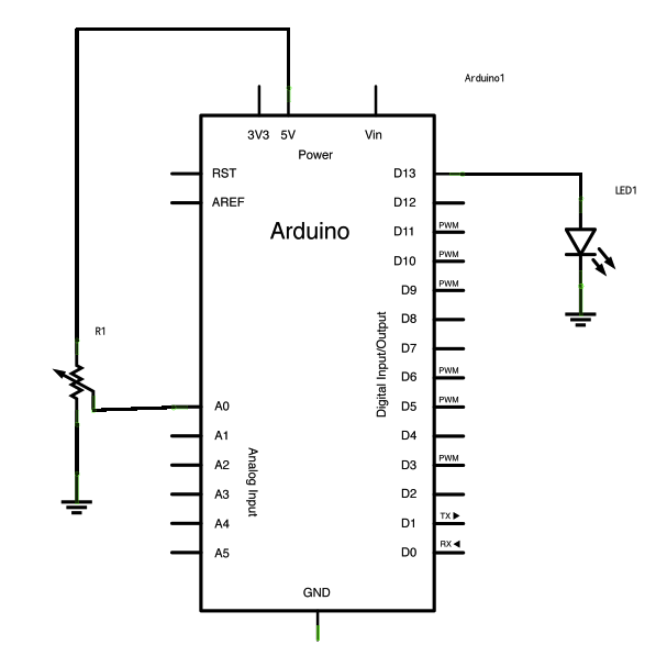
Circuit
image developed using Fritzing. For more circuit examples, see the Fritzing project page
Schematic:
Code
In the code below, a variable called analogValue is used to store the data collected from a potentiometer connected to the Arduino on analogPin 0. This data is then compared to a threshold value. If the analog value is found to be above the set threshold the LED connected to digital pin 13 is turned on. If analogValue is found to be < threshold, the LED remains off.
Hardware Required
- Arduino Board
- (1) Potentiometer or variable resistor
- (1) 220 ohm resistor
- (1) LED
- hook-up wire
For more detail: Potentiometer or variable resistor control LED Code
- What is the most basic programming control structure?
The if statement is the most basic of all programming control structures. - How does the if-else variation work?
It executes code if a condition is true, and runs alternative code if that condition is false. - When should you use else-if?
You use else-if to check a second condition only if the first condition is false. - Which pin is used for the built-in LED in the example?
The example turns on an LED connected to digital pin 13. - Where is the potentiometer connected?
The potentiometer is connected to analogPin 0 on the Arduino. - What happens if the analog value is below the threshold?
If the analogValue is less than the threshold, the LED remains off. - Can you check multiple conditions sequentially?
Yes, you can check a second condition using else-if if the first one fails.