Summary of PIR Motion Sensor With Arduino in Tinkercad
Summary: This lesson teaches detecting motion with a PIR sensor and Arduino using Tinkercad Circuits or a physical build. It covers wiring a PIR, LED, and resistor to Arduino pins, block-based and Arduino C code to read the sensor on a digital pin and drive an LED, sensor setup details, optional potentiometer adjustments, and next project ideas like servos or enclosures.
Parts used in the PIR Motion Sensor With Arduino:
- Arduino Uno
- USB cable
- Solderless breadboard
- LED
- Resistor (100–1K ohm)
- PIR motion sensor
- Breadboard jumper wires
We will learn how to detect movement in a space using a PIR motion sensor and Arduino’s digital input. We will set up a circuit with a breadboard and use basic Arduino code to manipulate a solitary LED. We will utilize Tinkercad Circuits to replicate the circuit, enabling you to follow the process without any physical components, and also demonstrate how to construct the actual circuit.
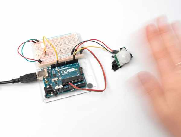
So far you’ve likely already learned to read a pushbutton with Arduino’s digital input, so we’ll build on those skills in this lesson. Although the motion sensor may seem complex with its dedicated circuit board, it is configured to send a HIGH or LOW signal in much the same way a pushbutton would.
PIR is short for Passive InfraRed and refers to the technology within that passively senses levels of infrared light, as opposed to emitting it like an infrared camera does to capture reflections. The white dome acts as a lens, broadening the field of view of the IR detector. The sensor starts with a default LOW signal, detects the incoming infrared light level, and switches to a HIGH signal for a specific duration when there is a change in light levels, indicating motion. It is capable of indicating if there is motion in a setting, however, it is unable to determine distance— in that case, you can think about utilizing an ultrasonic rangefinder, which is an analog input sensor.
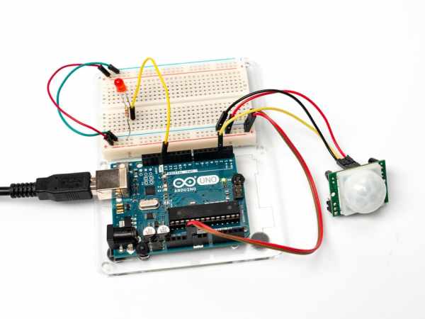
To build the physical circuit if desired, collect your Arduino Uno board, USB cable, solderless breadboard, LED, resistor (between 100-1K), PIR motion sensor, and breadboard wires.
You can follow along virtually using Tinkercad Circuits. You can even view this lesson from within Tinkercad (free login required)! Explore the sample circuit and build your own right next to it. Tinkercad Circuits is a free browser-based program that lets you build and simulate circuits. It’s perfect for learning, teaching, and prototyping.
Step 1: Build the Circuit
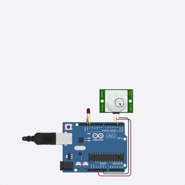
Explore the sample circuit here in the embedded circuit below by starting the simulation and clicking on the round motion sensor. This will activate a highlighted area in front of the sensor with a circle “object” inside. You may need to resize the view if the circle is off screen. Click and drag the “object” circle in front of the sensor to represent movement. The LED will turn on for a short time when movement is detected.
The free-wired version of this circuit is pictured above. If needed, take a moment to refresh your breadboard knowledge. You could load up a new Tinkercad Circuits window and build your own version of this circuit along side the sample.
Identify the PIR motion sensor, LED, resistor, and wires connected to the Arduino.
Drag an Arduino Uno and breadboard from the components panel to the workplane.
Connect breadboard power (+) and ground (-) rails to Arduino 5V and ground (GND), respectively, by clicking to create wires.
Extend power and ground rails to their respective buses on the opposite edge of the breadboard by creating a red wire between both power buses and a black wire between both ground buses.
Plug the LED into two different breadboard rows so that the cathode (negative, shorter leg) connects to one leg of a resistor (anywhere from 100-1K ohms is fine). The resistor can go in either orientation because resistors aren’t polarized, unlike LEDs, which must be connected in a certain way to function.
Connect other resistor leg to ground.
Wire up the LED anode (positive, longer leg) to Arduino pin 13.
Drag a PIR motion sensor from the components panel to your breadboard, so its legs plug into three different rows.
Click to create a wire connecting the rightmost leg to power.
Connect the center leg to ground.
Create a wire connecting the leftmost leg to Arduino analog pin A0.
Step 2: Code With Blocks
We will utilize the Blocks coding platform to monitor the PIR motion sensor and determine whether to illuminate an LED depending on whether the sensor is triggered or not.
Press the “Code” button in order to launch the code editor.
Select the Variables section in the code editor. Generate a fresh variable dubbed sensorState.
Pull a “set” block away.
Our variable sensorState will keep track of the state of our PIR motion sensor. Select the Input block category, move the “read digital pin” block, and place it inside the “set” block following the word “to”.
As our sensor is linked to the Arduino through Pin 2, adjust the dropdown menu of the “read digital pin” block to 2. Next, your blocks need to say “assign sensorState to obtain digital pin 2 reading,” which saves the digital reading of the sensor pin into our sensorState variable!
Select the Control section and pull out an “if then” block.
Set it up to check if sensorState is the same as HIGH using a Math comparator block. Place the Math comparator block into the if statement to verify if the variable sensorState is equal to HIGH.
Our goal is to activate the LED when the sensor is triggered, or else keep the LED off. Locate the block that says “set built-in LED to HIGH” in the Output block section. Incorporate two blocks into our if statement to ensure the LED is only lit when the sensor is triggered. The built-in LED should be set to HIGH if the sensor state is HIGH; otherwise, it should be set to LOW.
Step 3: PIR Motion Sensor Arduino Code Explained
When the code editor is open, you can click the dropdown menu on the left and select “Blocks + Text” to reveal the Arduino code generated by the code blocks. Follow along as we explore the code in more detail.
int sensorState = 0;
Before the setup(), we create a variable to store the current state of the sensor. It’s called int because it’s an integer, or any whole number (although we will only be using values 0 and 1, LOW and HIGH).
void setup()
{
  pinMode(2, INPUT);
  pinMode(13, OUTPUT);
  Serial.begin(9600);
}
Within the arrangement, pins are set up utilizing the pinMode() method. Pin 2 is set up as an input so that we can monitor the electrical status of the sensor. Pin 13 is set up as an output for managing the LED. In order to transmit messages, the Arduino initiates a fresh serial communication connection through Serial.begin(), specifying a baud rate (communication speed) of 9600 bits per second.
void loop()
{
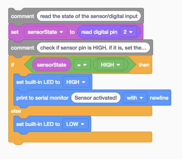
// read the state of the sensor/digital input
sensorState = digitalRead(2);
Anything after a set of slashes // is a comment, just for us humans to read, and is not included in the program when the Arduino runs it. In the main loop, a function called digitalRead(); checks the state of pin 2 (which will be either 5V aka HIGH or ground aka LOW), and stores that state in the sensorState variable we created at the top.
  // check if sensor pin is HIGH. if it is, set the
  // LED on.
  if (sensorState == HIGH) {
    digitalWrite(13, HIGH);
    Serial.println("Sensor activated!");
  } else {
    digitalWrite(13, LOW);
  }
  delay(10); // Delay a little bit to improve simulation performance
}
Below two more comment rows is an if statement that checks to see if sensorState is HIGH (== is a comparison operator, not to be confused with =, which is an assignment operator). If the condition is met, the built-in LED is set HIGH (on). If not, the code contained inside the else { is executed instead: the built-in LED is set LOW (off). If statements can exist alone, or with one or more else statements.
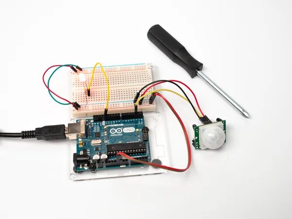
Step 4: PIR Motion Sensor Setup
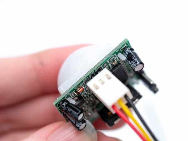
When creating a physical circuit, some preparation is required for your PIR motion sensor.
Determine the line of three titles on the circuit board. They will be located near the central edge and will be marked as GND, OUT, and +5v (or similar).
Connect the provided wired connector to the three header pins, making sure the black wire aligns with GND.
Make sure the connector is securely plugged in.
Instead, you have the option to attach three separate female-to-male prototyping wires to the header pins.
Step 5: Build a Physical Arduino Circuit (Optional)
To program your physical Arduino Uno, you’ll need to install the free software (or plugin for the web editor), then open it up.
Wire up the Arduino Uno circuit by plugging in components and wires to match the connections shown here in Tinkercad Circuits. For a more in-depth walk-through on working with your physical Arduino Uno board, check out the free Instructables Arduino class.
Copy the code from the Tinkercad Circuits code window and paste it into an empty sketch in your Arduino software, or click the download button (downward facing arrow) and open the resulting file using Arduino. You can also find this example in the Arduino software by navigating to File -> Examples -> 02.Digital -> Button (with a different variable name but it’s otherwise the same).
Plug in your USB cable and select your board and port in the software’s Tools menu.
Upload the code and watch your LED light up when you move in front of the sensor!
Step 6: PIR Motion Sensor Adjustments
Certain PIR motion detectors feature a pair of adjustable potentiometers to modify the sensitivity and duration of the activation signal. The PIR motion sensor in Tinkercad Circuits is unable to mimic these changes.
You can use a small screwdriver if you’d like to modify the sensitivity and time settings on the circuit board of your PIR motion sensor. Conduct a test to observe how it influences the performance of the circuit.
Step 7: Next, Try…
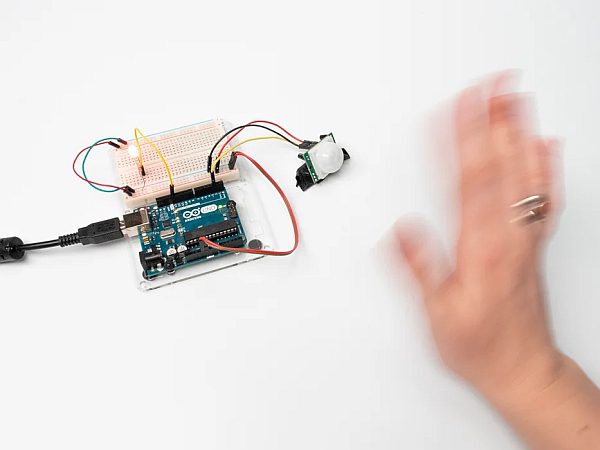
Now that you’ve learned to detect a PIR motion sensor’s signal and use if statements to evaluate its state, you’re ready practice more coding and even build your sensor into a finished project.
Can you replace the LED with a servo motor, and code up a program to wave the servo when the sensor is triggered?
Try the 3D printing side of Tinkercad to build an electronics enclosure with an opening for your PIR motion sensor.
Try swapping out your PIR motion sensor for other digital inputs such as a pushbutton or tilt switch.
Learn how to monitor your Arduino’s digital and analog inputs through the computer using the Serial Monitor.
You can also learn more electronics skills with the free Instructables classes on Arduino, Basic Electronics, LEDs & Lighting, 3D Printing, and more.
Source: PIR Motion Sensor With Arduino in Tinkercad
- How is the PIR motion sensor connected to the Arduino?
Connect PIR power to Arduino 5V, PIR ground to Arduino GND, and PIR output to a digital pin (example uses pin 2); connect LED anode to pin 13 and cathode through a resistor to ground. - Can I simulate the circuit without physical components?
Yes, you can replicate and simulate the circuit in Tinkercad Circuits and trigger the sensor in simulation by dragging the object in front of the sensor. - What code reads the PIR sensor and controls the LED?
The code reads digital pin 2 with digitalRead, stores it in sensorState, and uses an if statement to set the LED on pin 13 HIGH when sensorState is HIGH, otherwise sets it LOW. - How do I prepare the PIR sensor for a physical build?
Identify the three pins labeled GND, OUT, and +5V, attach the connector making sure the black wire is on GND, or use three female-to-male wires to connect them. - Does the PIR sensor measure distance?
No, the PIR sensor detects changes in infrared levels to indicate motion but cannot determine distance; an ultrasonic rangefinder is suggested for distance measurement.