Summary of [Password Box] Arduino One Touch Password Input (USB Keyboard Hack)
Summary: This project converts an old PC keyboard into an Arduino-driven Password Box that types stored passwords on demand. It scans the keyboard matrix, drives selected row/column lines to emulate key presses, and adds RFID-based access control so only authorized cards can trigger password entry. The device uses an Arduino Mega, RFID module, switches, and LEDs housed in a plastic case.
Parts used in the Password Box:
- Old PC keyboard (disassembled PCB and button pad)
- Arduino Mega2560
- USB Keyboard (unused)
- RFID module (MFRC522)
- RFID card(s)
- 4x Switches
- 2x LEDs
- Wires and connectors
- Plastic case
Today is the world of internet social. We have many social platform Email, Facebook, Instagrams, Twitter, Instructables and etc.For security issue we should not use the same password for these platform and some platform enforce us to create password that difficult to remember. It is better to write it to your notebook but some people was boring to type their password (espcially me).
Step 1: Explore Your Keyboard
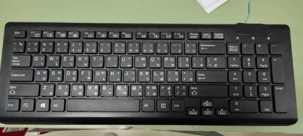
I used some old keyboard in this project. After disassemble we have two main parts, one is PCB and another is button pad.
Step 2: Track All Key
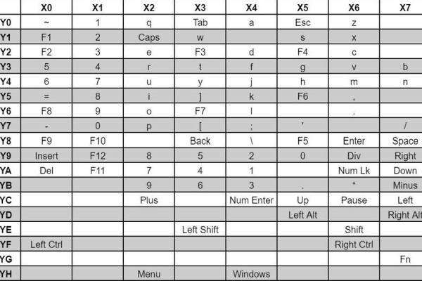
On PCB we found two groups of pin X and Y. After tracking all button wire from Xn to Yn we got Key mapping
In this we use a-z, A-Z, 0-9 and some special characters. So, Y0-Y8 and YE on PCB are use.
Step 3: Matrix Key Scan
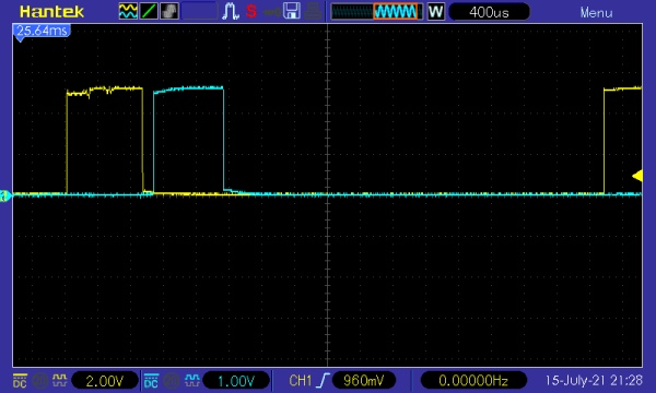
PC keyboard has more than a hundred keys. Matrix scan is used to reduce input output of processor.
The image of oscilloscope shows X0 and X1 output signal. We can confirm that this keyboard is scan from X0 to X7.
Assume that we need keyboard to send(press) key ‘A’ to PC, As you see in the key mapping table above, We need to wait X4 logic High, Then drive Y0 to High. Beware to drive Y0 High when other than X4 is High, Otherwise you will get other characters. Do it for other key in same step but difference Xn and Yn.
Step 4: Add RFID for More Security
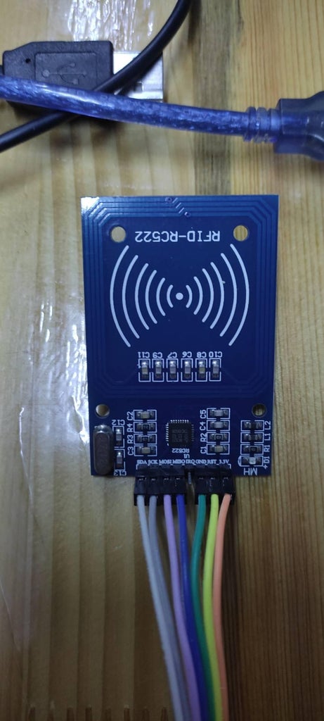
This project I add RFID to protect our password box. Only person who has certain RFID card will allow to use the password box.
I use RFID library from https://github.com/miguelbalboa/rfid
Step 5: Combine All
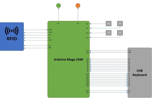
All hardware
1x Arduino Mega2560
1x USB Keyboard (unused)
1x RFID Module
4x Switches
2x LEDs
1x Plastic Case
Step 6: Coding
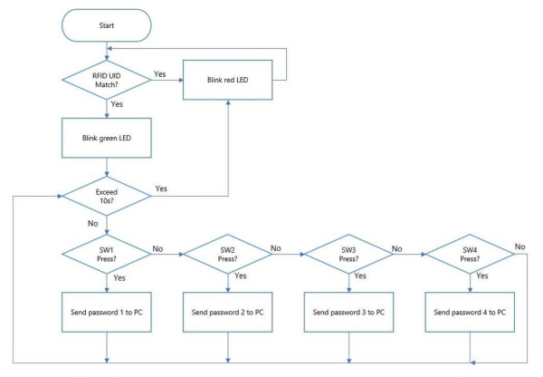
I use Arduino IDE to programming this project.
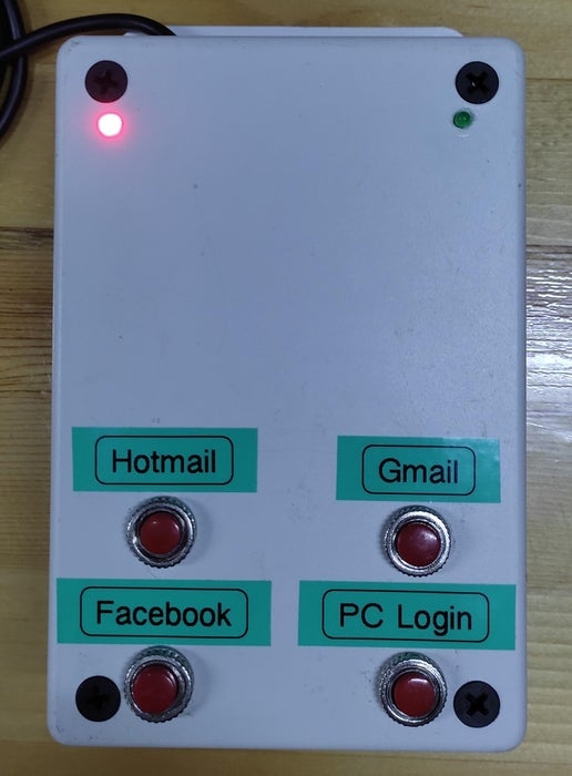
As you see the image after attach Password Box to your PC, The Password Box initialize peripheral hardware and red LED will indicates. Until certain card was scan by MFRC522 you will allow to use Password box to enter password to desire platform.
Step 7: Using Password Box
Source: [Password Box] Arduino One Touch Password Input (USB Keyboard Hack)
- What is the main purpose of the Password Box?
To emulate keyboard key presses to input stored passwords and restrict access via RFID. - How does the project detect which key to press?
By mapping the keyboard matrix pins X and Y and driving the appropriate Y when a specific X is scanned high. - Can any keyboard be used for this project?
An old PC keyboard is used in the project after disassembly into PCB and button pad. - How is security implemented in the device?
Security is implemented using an RFID module so only certain RFID cards allow use. - What microcontroller is used to control the Password Box?
Arduino Mega2560 is used in this project. - Which pins on the keyboard PCB were used for characters?
Y0 through Y8 and YE on the PCB were used for characters including a-z, A-Z, 0-9 and some special characters. - What library is used for the RFID module?
The MFRC522 RFID library from github.com/miguelbalboa/rfid is used. - How does the device indicate it is waiting for an authorized card?
The device initializes peripherals and lights a red LED until an authorized card is scanned. - What development environment is used to program the device?
Arduino IDE is used to program the project. - Are there any unused components mentioned?
Yes, a USB Keyboard is listed as unused.